


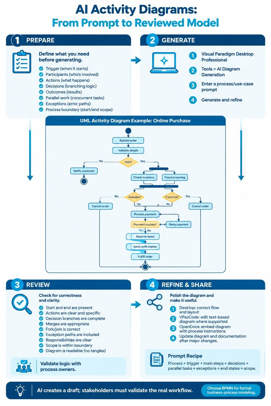
In modern software engineering and business process management, the gap between abstract requirements and concrete technical models is often bridged by AI. Visual Paradigm Desktop Professional has introduced a powerful workflow that transforms written process descriptions into structured UML activity diagrams. This tutorial explores the system architecture of this feature, the underlying modeling logic demonstrated in the “Online Purchase” example, and the critical role of human validation in the loop.
The Workflow Architecture: From Concept to Model
The process of generating an activity diagram via AI is not merely a text-to-image conversion; it is a structured architectural pipeline. Visual Paradigm breaks this workflow into four distinct phases: Prepare, Generate, Review, and Refine. This ensures that the resulting diagram is not just a visual artifact, but a logical representation of a defined process.
Phase 1: Preparation (The Input Layer)
Before any generation occurs, the system requires a well-defined context. The AI cannot infer the boundaries of a system without explicit instruction. In this phase, the user must define:
- Triggers: What initiates the process? (e.g., “User submits order”)
- Participants: Who is involved? (e.g., “Customer,” “Inventory System,” “Payment Gateway”)
- Actions: What specific steps occur? (e.g., “Validate details,” “Check inventory”)
- Decisions: Where does logic branch? (e.g., “Is inventory available?”)
- Exceptions: How are errors handled? (e.g., “Notify customer” if validation fails)
Phase 2: Generation (The Synthesis Layer)
Once the input is structured, the user invokes the feature via Tools > AI Diagram Generation in the Visual Paradigm Desktop Professional edition. The AI engine parses the prompt and synthesizes the UML model. It identifies:
- Nodes: The start, end, and activity states.
- Edges: The control flows connecting the actions.
- Structural Elements: Forks (parallel processing), Joins (synchronization), and Decision diamonds (conditional logic).
Phase 3: Review (The Quality Assurance Layer)
The AI produces a draft. The user must verify the logical integrity of the diagram. Key checks include ensuring that every decision node has a corresponding exit path, that the start and end nodes are present, and that the diagram is free of “tangles” or unconnected flows.
Phase 4: Refine & Share (The Deployment Layer)
In the final stage, the model is polished. This involves using the VPasCode tool for text-based edits where the visual UI might be cumbersome, or utilizing OpenDocs to embed the diagram directly into documentation. The prompt recipe suggests a formula: Process + Trigger + Main Steps + Decisions + Parallel Tasks + Exceptions + End States + Scope.
Deconstructing the “Online Purchase” Model
The provided example illustrates a classic “Happy Path” scenario with embedded exception handling. Let us analyze the logic flow depicted in the diagram to understand the underlying UML mechanics.
1. The Entry and Validation Gate
The process begins at the black circle (Initial Node) and moves to Submit order. Immediately, the flow encounters a decision diamond labeled Valid?. This is a critical gatekeeping mechanism. If the data is invalid, the flow immediately diverges to Notify customer and terminates at the final node. This demonstrates the importance of defining error paths (negative flows) alongside success paths.
2. The Fork and Parallelism
Upon a “Yes” (Valid) result, the control flow reaches a thick horizontal bar. In UML terminology, this is a Fork. It splits the single thread of control into two concurrent threads:
- Thread A: Check inventory
- Thread B: Fraud screening
This parallelism represents efficiency in real-world systems—checking stock and verifying creditworthiness often happen simultaneously to reduce latency.
3. The Join and Synchronization
Following the parallel tasks, the flow reaches a second thick bar. This is a Join. The process cannot proceed to payment processing until both the inventory check and the fraud screening have completed and returned results. This synchronization point is vital for data integrity.
4. Conditional Logic and Loops
The flow then splits again based on the results of the checks:
- If Inventory is “No” (Unavailable), the process loops back to Cancel order.
- If Fraud Risk is “Yes” (High Risk), the process also loops back to Cancel order.
- If both are clear, the process proceeds to Process payment.
A nested loop exists here: if Payment success? is “No,” the flow directs to Retry payment, which then feeds back into the payment action. This recursive structure handles transient errors gracefully.
Technical Modeling Concepts Explained
Understanding the visual elements allows you to communicate effectively with the AI and interpret its output. The diagram relies on standard UML 2.0 Activity Diagram notation.
Decision Nodes vs. Fork/Join Nodes
It is crucial to distinguish between a diamond shape and a bar. A diamond represents a Decision Node (e.g., “Valid?”), which routes control to one of several paths based on a condition. A bar represents a Fork or Join, which splits or merges control flows to manage concurrency.
Control Flow vs. Object Flow
In this diagram, we primarily see Control Flow (solid arrows), indicating the order of execution. If we were modeling the movement of data (like an Order object moving from “Submit” to “Process”), we would use Object Flow (often dashed lines). The AI correctly interprets the prompt as a control flow of actions.
Refining with VPasCode
For advanced users, the Visual Paradigm text-based modeling tool, VPasCode, offers a programmatic way to refine the diagram generated by AI. While the AI creates the structure, VPasCode allows for precise syntax control.
For instance, if the AI generates a generic “Process Payment” node, you might use VPasCode to define specific sub-activities or add detailed annotations that the visual editor might not immediately render. The workflow supports a “Draft” approach where the AI provides the skeleton, and the engineer provides the muscle.
The Human-in-the-Loop Mandate
The footer of the workflow emphasizes a critical industry standard: “AI creates a draft; stakeholders must validate the real workflow.” AI is a generator of possibilities, not a validator of business truth. It may interpret “Notify customer” as a simple text message when the business logic actually requires a phone call or an SMS. Therefore, the final step is always validation with process owners to ensure the model matches the reality of the business.
Conclusion
By leveraging Visual Paradigm’s AI tools, teams can rapidly transition from text-based requirements to executable models. The key lies in the structured preparation of the prompt and the rigorous review of the generated logic. Whether analyzing the “Online Purchase” scenario or designing complex enterprise workflows, the combination of AI efficiency and human oversight creates robust, validated system architectures.