


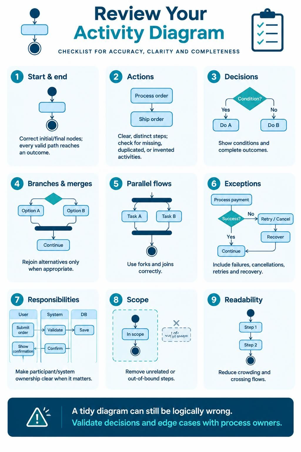
Creating an activity diagram is often the most visual part of the software design process, but it is frequently the most prone to subtle logic errors. A diagram can look perfectly clean and professional while containing fundamental flaws in its control flow. To ensure your models are robust, scalable, and logically sound, you must adopt a rigorous review protocol.
This guide walks you through the essential checklist for reviewing activity diagrams, focusing on the critical components of Start/End nodes, Actions, Decisions, and Exception handling. We will explore these concepts using a high-level, discussion-based approach suitable for architects and technical leads.
1. The Foundation: Start and End Nodes
The lifecycle of any software process begins with a specific trigger and concludes with a definitive outcome. In activity modeling, these are represented by the Start Node (a filled circle) and the End Node (a circle with a thick border).
When reviewing your diagrams, you must verify two critical rules:
- Correct Placement: The flow must originate from a single initial point. While complex systems may have multiple entry points, they should typically funnel into a single logical start for the specific scenario being modeled.
- Path Completeness: Every valid path in your diagram must eventually reach an outcome. A common error is creating “orphaned” paths that lead to nowhere. If a user clicks a button and the system goes into a loop or a dead end, the diagram is incomplete.
2. Defining Actions
Actions are the workhorses of your workflow. They represent atomic operations, such as “Calculate Tax,” “Validate Input,” or “Send Email.” When auditing the Actions section of your diagram, look for the following:
- Clarity and Distinctness: Each action should represent a single, distinct step. Avoid combining unrelated tasks (e.g., “Process and Save”) in a single node unless they are logically inseparable.
- Completeness Check: Are there missing steps? For example, does the diagram show a “Save” action? Are there duplicated activities where the same process is modeled twice in different branches?
- Invented Activities: Ensure that every step shown actually exists in the real-world workflow. Do not invent features or processes to make the logic “look good.”
3. The Logic of Decisions
Decisions (represented by diamonds) introduce branching logic into your diagram. This is often where the most complex business rules reside. A review of the Decisions section must answer two questions:
1. Are Conditions Explicit? Every outgoing path from a decision node must have a label defining the condition (e.g., Valid?, Yes/No, Amount > 100). If a path has no label, the diagram is ambiguous.
2. Are Outcomes Complete? Do the paths cover all possibilities? In a binary decision, you typically expect a “True” and “False” path. If a logic gate allows for an “Unknown” state that isn’t handled, your model is flawed.
4. Branches and Merges
Branches allow the workflow to split based on logic, but they must eventually come back together. This rejoining point is called a Merge Node.
The Rule of Appropriateness: Alternative paths should only rejoin when the system state is identical again. If you split the flow to perform two different actions, you must merge them back into a single flow before proceeding to the next shared step. Merging too early (before the distinct actions are complete) or too late (after the paths have diverged significantly) creates logical confusion.
5. Parallel Flows (Forks and Joins)
Not all processes are linear. Sometimes, tasks happen simultaneously. In activity diagrams, this is represented by Forks (splitting into parallel threads) and Joins (recombining them).
When reviewing parallel flows:
- Synchronization: Ensure that the Join node waits for all incoming parallel threads to complete. If one thread finishes and the other is still running, the Join node holds up the flow.
- Correct Placement: Are concurrent activities represented correctly? Do not use a standard decision diamond to represent parallel execution; use the specific fork/join bars (thick horizontal lines).
6. Handling Exceptions
Real-world systems fail. A perfect diagram that assumes everything goes right is rarely useful. The “Exceptions” section of your review must verify that the diagram accounts for the “Happy Path” versus the “Unhappy Path.”
Key Exception Scenarios:
- Failures: What happens if a database connection drops?
- Cancellations: Can the user abort the process midway?
- Retries and Recovery: If a payment fails, is there a retry loop? Is there a recovery path to a safe state?
If your diagram lacks these paths, it is incomplete. Ensure that error paths eventually merge back into a valid state or lead to a distinct failure end node.
7. Responsibilities (Swimlanes)
Activity diagrams are often divided into swimlanes to show Who is performing What. This is critical for system design.
Ownership Clarity: Make sure the diagram clearly distinguishes between actions performed by the User, the Application System, the Database, or External Services. If a node is ambiguous—sitting on a line that crosses swimlanes without a clear owner—it can lead to development errors where the wrong developer builds the wrong logic.
8. Defining Scope
A common mistake is “Scope Creep,” where the diagram tries to model too much. The review process must identify steps that do not belong to the current process boundary.
Boundary Enforcement: Remove steps that belong to a different process or are outside the agreed boundary. If your diagram is for “Order Processing,” do not include the “Manufacturing” steps that happen weeks later unless they are relevant to the specific decision logic you are modeling. Keep the diagram focused.
9. Readability and Layout
Finally, a diagram must be readable. If the reviewer has to trace the lines with their finger to understand the flow, the diagram has failed its communicative purpose.
Visual Hygiene: Rearrange crowded nodes or crossing flows. While tools like Visual Paradigm can auto-layout diagrams, manual adjustments are often necessary to ensure that the flow is top-to-bottom or left-to-right without unnecessary crossings. A visually tidy diagram is easier to audit for logical errors.
The Golden Rule of Validation
It is crucial to remember that a diagram can be visually perfect but logically incorrect. A tidy diagram can still contain incorrect logic.
Therefore, the final step of your review is not a visual check, but a logical one. Validate your decisions, edge cases, and exception paths directly with the people who own the process. The diagram is a contract between the design team and the business; it must be accurate, not just pretty.