


Unified Modeling Language (UML) provides a standardized way to visualize the design of a system. However, standard UML is often too generic for specific domains or specialized technologies. This is where the concept of a UML Profile becomes essential. A profile diagram allows architects and developers to extend the standard UML metamodel to fit unique project requirements without altering the core language.
Creating a profile diagram involves defining stereotypes, tagged values, and constraints. It enables teams to model specific architectural patterns, security protocols, or database schemas using familiar visual notation. This guide details the mechanics, benefits, and best practices for developing robust UML profiles.
🔍 What is a UML Profile Diagram?
A UML Profile is a mechanism for extending the UML metamodel. It allows you to create new modeling elements based on existing UML elements. Think of it as a set of rules and additions that sit on top of the standard UML language.
- Standard UML: Covers general software engineering concepts like classes, interfaces, and use cases.
- UML Profile: Customizes these concepts for a specific context, such as web services, embedded systems, or cloud infrastructure.
When you create a profile diagram, you are essentially defining a vocabulary that your team can use within a modeling tool. This vocabulary remains consistent across all diagrams that import the profile.
🧩 Core Components of a Profile
To build a functional profile, you must understand its three primary building blocks. Each block serves a distinct purpose in defining how a model element behaves or is described.
1. Stereotypes
Stereotypes are the most visible part of a profile. They allow you to classify a standard UML element in a new way. They are typically displayed using double angle brackets, such as <<MyStereotype>>.
- Function: Indicates a specialized type of a UML element.
- Example: Extending a standard Class to represent a Database Table.
2. Tagged Values
Tagged values allow you to add metadata to an element. They act like custom properties that are not part of the standard UML structure.
- Function: Stores specific data associated with a model element.
- Example: Adding a “TableSize” attribute to a Database Table class.
3. Constraints
Constraints are rules that restrict the behavior or structure of a model element. They are often written in a formal language like OCL (Object Constraint Language) or simply as text.
- Function: Enforces business rules or technical limits.
- Example: Ensuring a specific attribute cannot be null.
Comparison of Profile Elements
| Element | Purpose | Visual Representation |
|---|---|---|
| Stereotype | Extends the classification of an element | <<Stereotype>> |
| Tagged Value | Stores custom metadata | name = value |
| Constraint | Imposes rules or conditions | {condition} |
🚀 Why Use Profile Diagrams?
Using a profile diagram is not just about adding complexity; it is about improving clarity and precision. Here are the primary reasons to implement profiles in your modeling strategy.
- Domain Specificity: General UML terms might be ambiguous in specialized fields. Profiles define terms like “Microservice” or “API Endpoint” clearly.
- Tool Integration: Many modeling tools rely on profiles to generate code or documentation. A well-defined profile ensures the tool understands your intent.
- Consistency: By defining a profile once, all team members use the same terminology. This reduces miscommunication during code reviews or design meetings.
- Reusability: Once a profile is created, it can be applied to multiple projects. This saves time on defining standard patterns repeatedly.
- Documentation: Profiles serve as living documentation. They describe not just the structure, but the rules governing the system.
🛠️ Step-by-Step Process for Creating a Profile
Creating a profile requires a structured approach. While specific tools may vary, the logical steps remain consistent across the industry.
Step 1: Define the Namespace
Every profile must exist in its own namespace to avoid conflicts with standard UML elements or other profiles. This namespace acts as a unique identifier for your extension.
- Select a unique URI or string for the namespace.
- Ensure this namespace does not overlap with existing libraries.
Step 2: Identify Base Types
You need to decide which standard UML elements you want to extend. Common base types include:
- Class: Used to define data structures or components.
- Interface: Used for defining contracts or services.
- Package: Used to group related elements.
- Association: Used to define relationships between elements.
Step 3: Create Stereotypes
For each extension, create a stereotype that inherits from the chosen base type. This creates a new classification within the UML hierarchy.
- Open the profile editor or diagram canvas.
- Create a new stereotype element.
- Link it to the base UML element (e.g., Class).
Step 4: Add Tagged Values
Once the stereotype is defined, determine what metadata is necessary. Add tagged values to the stereotype definition.
- Define the name of the tag (e.g., “Version”, “Owner”, “Status”).
- Define the data type (String, Integer, Boolean).
- Set a default value if applicable.
Step 5: Apply Constraints
If your extension requires specific rules, add constraints. These ensure that models using the profile adhere to architectural standards.
- Write the constraint text or OCL expression.
- Link the constraint to the stereotype or the base element.
- Ensure the constraint is testable within your modeling environment.
Step 6: Save and Import
Finalize the profile and save it to your library. To use it in a project, import the profile into the relevant modeling package.
- Locate the profile file in your storage.
- Select the “Import Profile” option in your modeling environment.
- Verify that the new stereotypes appear in the palette.
📐 Anatomy of a Profile Diagram
A profile diagram is a specific type of UML diagram. Its layout is designed to show the structure of the extensions rather than the flow of data. It typically contains the following sections.
- Profile Package: The container for all profile definitions.
- Base Model Elements: References to the standard UML elements being extended.
- Extension Elements: The new stereotypes and attributes defined in the profile.
- Relationships: Lines showing how the new elements relate to the base elements.
When viewing the diagram, you should see a clear distinction between the standard UML kernel and your custom extensions. This visual separation helps users understand what is native and what is custom.
📋 Best Practices for Modeling Profiles
To ensure your profiles remain useful and maintainable, follow these guidelines.
1. Keep Profiles Minimal
Do not add every possible attribute to a stereotype. Only include tagged values that are strictly necessary for the domain. Excessive metadata complicates the model and slows down tools.
2. Use Clear Naming Conventions
Names should be descriptive and consistent. Avoid abbreviations that might confuse new team members. If you use a prefix, apply it consistently across all stereotypes.
3. Document the Purpose
Every profile should have a clear description. Explain why the profile exists and what problem it solves. This documentation is vital for long-term maintenance.
4. Version Control
Profiles evolve. If you change a stereotype, it might break existing models. Use versioning for your profile files to track changes over time.
5. Separate Concerns
Do not create one massive profile for everything. Split profiles by domain (e.g., Security Profile, Database Profile, Web Profile). This makes it easier to manage dependencies.
⚠️ Common Mistakes to Avoid
Even experienced modelers can make errors when creating profiles. Being aware of these pitfalls can save significant time.
- Over-Extending: Trying to model every business rule in the profile. Profiles should focus on structural extensions, not complex logic.
- Ignoring Base Types: Creating stereotypes that do not inherit from a valid UML element. This breaks compatibility with standard tools.
- Conflicting Names: Using a stereotype name that already exists in the standard UML library. Always check for name collisions.
- Lack of Testing: Applying the profile to a model without verifying that the stereotypes render correctly. Always validate the profile against a test model.
- Hardcoding Values: Using specific values in constraints instead of variables. This makes the profile rigid and less reusable.
🔄 Maintenance and Evolution
A profile is not a one-time setup. As your technology stack changes, your profiles must adapt. Here is how to handle evolution.
Updating Existing Profiles
When updating a profile, check all models currently using it. You may need to migrate existing elements to the new stereotype version. Communication is key. Notify all users of the change before deploying the update.
Deprecating Elements
If a stereotype is no longer needed, do not delete it immediately. Mark it as deprecated. This allows older models to remain valid while encouraging the migration to new standards.
Compatibility Checks
Ensure that new profiles remain compatible with older versions of UML. If you rely on a specific version of the UML standard, document this requirement clearly.
🔗 Integration with Standard UML
Profiles do not replace standard UML; they augment it. When creating a profile diagram, remember that the standard elements are always available. You can mix standard classes with profile stereotypes in the same diagram.
For example, you might have a standard “Class” element representing a generic object, and a “<<Service>> Stereotype” representing a microservice. Both can coexist in the same diagram, allowing for a hybrid view of the system.
Dependency Management
Profiles often depend on other profiles. For instance, a “Security Profile” might depend on a “Network Profile”. Manage these dependencies carefully. Circular dependencies can cause modeling errors.
- Map out the dependency chain before building.
- Load base profiles first.
- Load dependent profiles last.
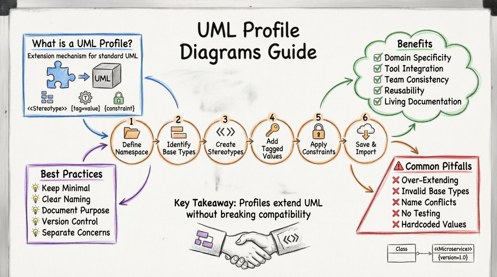
📝 Summary of Key Takeaways
- UML profiles extend the standard language for specific domains.
- The three main components are Stereotypes, Tagged Values, and Constraints.
- Profiles improve consistency, documentation, and tool integration.
- Follow a step-by-step process: Namespace, Base Types, Stereotypes, Tags, Constraints.
- Maintain profiles with versioning and clear documentation.
- Avoid over-complicating the model with unnecessary metadata.
- Always ensure compatibility with the standard UML metamodel.
By mastering the creation of UML profile diagrams, you empower your team to model complex systems with precision. This approach bridges the gap between abstract theory and concrete implementation, ensuring that your architectural designs are both accurate and actionable.