


Unified Modeling Language (UML) provides a standard syntax for describing software systems. However, standard UML diagrams often lack the specificity required for specialized domains. This is where the UML Profile Diagram becomes essential. Profiles allow modelers to extend the language with domain-specific stereotypes, tagged values, and constraints without altering the core standard. This guide explores practical applications of UML Profiles across various industries.
By examining real-world scenarios, we can understand how these extensions improve communication, validation, and documentation. We will look at how profiles structure data in healthcare, manage timing in automotive systems, and enforce security rules in finance. Each example demonstrates the technical mechanics of profile application and the resulting benefits.
Understanding the Core Components 🧩
Before diving into specific case studies, it is necessary to define the building blocks of a UML Profile. A profile consists of three primary elements:
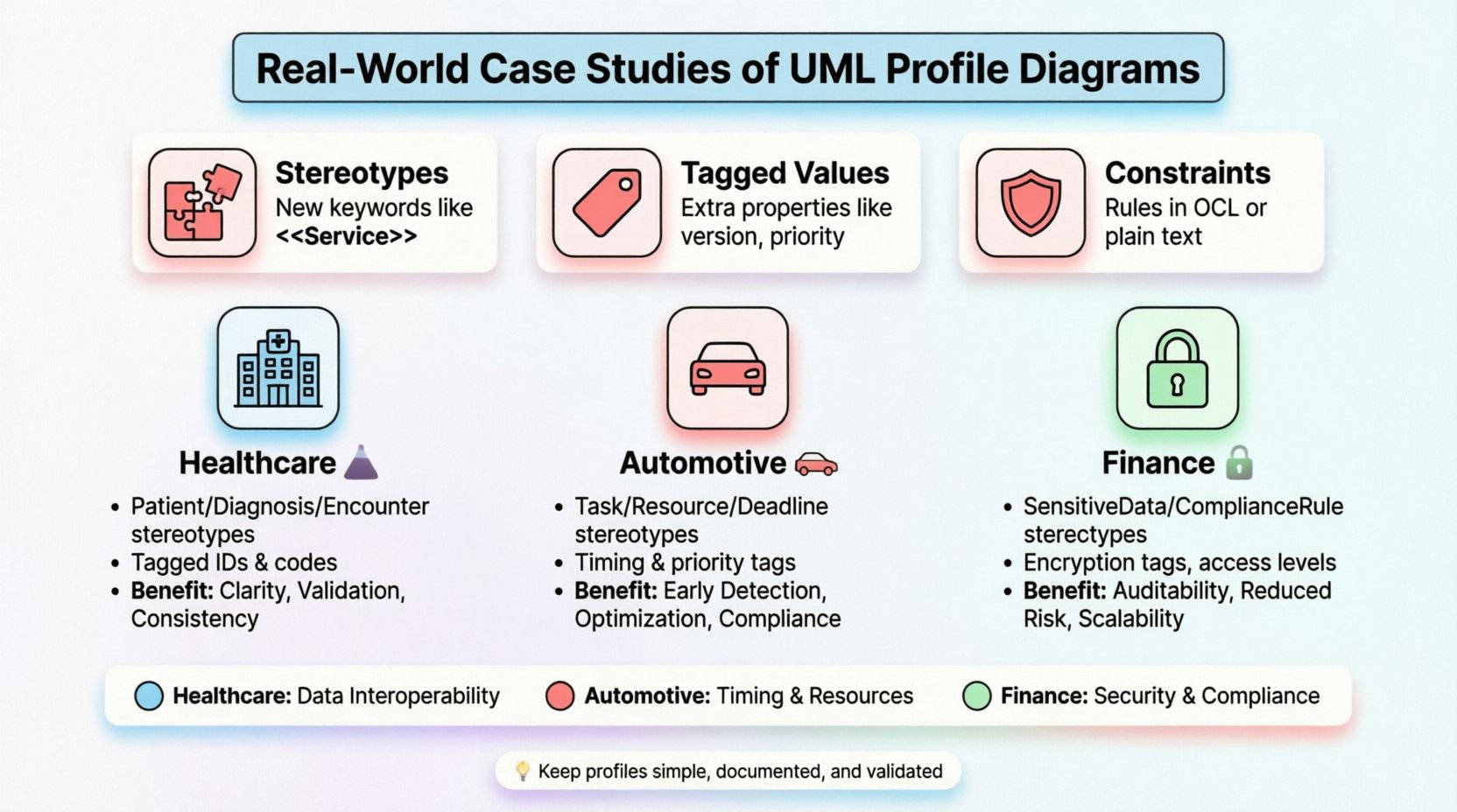
- Stereotypes: These act as new keywords or categories for model elements. For example, a standard
Classmight become a<<Service>>class to indicate its function within a specific architecture. - Tagged Values: These allow additional properties to be attached to model elements. Examples include version numbers, priority levels, or specific data types not covered by the base UML.
- Constraints: These define rules that must be satisfied for the model to be valid. Constraints are often expressed in Object Constraint Language (OCL) or plain text.
These components work together to create a tailored vocabulary. This vocabulary ensures that all stakeholders in a project speak the same language regarding domain-specific requirements.
Case Study 1: Healthcare Data Interoperability 🏥
Healthcare systems require strict adherence to data standards to ensure patient safety and privacy. Standard UML class diagrams do not inherently support the complex metadata required for medical records. A custom profile was developed to map patient data structures to industry standards.
Profile Structure
The profile introduced specific stereotypes for medical entities. The following list outlines the key elements:
<<Patient>>: An extension of theClassstereotype representing a specific individual.<<Diagnosis>>: A specialized element for medical conditions, including attributes for severity and classification codes.<<Encounter>>: Represents an interaction between a provider and a patient, tagged with timestamps and location details.
Implementation Details
In this scenario, the profile was applied to a system managing electronic health records. The goal was to ensure that data models aligned with international exchange standards. Tagged values were used to store critical identifiers such as patient IDs and insurance codes directly within the diagram.
Constraints were defined to prevent data integrity errors. For instance, a constraint was added to ensure that a Diagnosis element always links to a valid Patient element. This logic is enforced during model validation, catching errors before code generation.
Benefits Realized
The adoption of this profile yielded several tangible advantages:
- Clarity: Developers and medical staff could read the diagrams without needing external documentation.
- Validation: Automated tools could check the model against regulatory requirements.
- Consistency: All teams used the same terminology, reducing miscommunication during handoffs.
Case Study 2: Automotive Embedded Systems 🚗
Automotive engineering involves complex interactions between hardware and software. Timing and resource management are critical. Standard UML activity diagrams often fail to capture the real-time constraints necessary for embedded controllers. A profile was created to model these temporal aspects explicitly.
Profile Structure
This profile extended the UML state machine and class diagrams to include timing information. The primary components included:
<<Task>>: Represents a software task with defined execution periods.<<Resource>>: Denotes hardware resources such as CPU cores or memory blocks.<<Deadline>>: A constraint tag indicating the maximum allowable response time for a specific operation.
Implementation Details
The modelers attached tagged values to tasks specifying their execution time and priority. This allowed the system architecture to be simulated before physical deployment. Constraints were used to define relationships between tasks and resources.
For example, a constraint ensured that high-priority safety tasks could not be blocked by low-priority infotainment tasks. This logic was verified using schedulability analysis tools. The profile provided the necessary metadata for these tools to function correctly.
Benefits Realized
The implementation of this profile improved the development lifecycle significantly:
- Early Detection: Timing violations were identified during the design phase, not during testing.
- Optimization: Engineers could visualize resource contention and optimize allocations.
- Compliance: The model adhered to safety standards required for automotive certification.
Case Study 3: Financial Transaction Security 🔒
Financial institutions handle sensitive data that requires rigorous protection. Standard security protocols are often implemented generically, leading to gaps in specific transaction flows. A profile was designed to annotate data flows with security requirements and compliance markers.
Profile Structure
The security profile focused on data classification and access control. Key elements included:
<<SensitiveData>>: Marks data elements requiring encryption.<<ComplianceRule>>: Attaches specific regulatory requirements to data stores.<<AccessLevel>>: Defines the clearance level required to access a specific component.
Implementation Details
Modelers applied these stereotypes to sequence and component diagrams. Tagged values specified the type of encryption required (e.g., AES-256) and the key management strategy. Constraints ensured that sensitive data never flowed through unauthorized channels.
For instance, a constraint prevented a PublicAPI component from directly accessing a <<SensitiveData>> store. This enforced a separation of concerns that simplified the security audit process.
Benefits Realized
The security profile delivered measurable improvements:
- Auditability: Regulators could trace data protection requirements directly in the model.
- Reduced Risk: Security vulnerabilities were less likely to be introduced during implementation.
- Scalability: Security policies could be updated by modifying the profile, rather than rewriting every diagram.
Comparison of Profile Applications 📊
The following table summarizes the differences between the profiles discussed. This comparison highlights how domain needs dictate profile structure.
| Domain | Primary Focus | Key Stereotype | Constraint Type |
|---|---|---|---|
| Healthcare | Data Interoperability | <<Patient>> |
Referential Integrity |
| Automotive | Timing & Resources | <<Task>> |
Schedulability |
| Finance | Security & Compliance | <<SensitiveData>> |
Access Control |
Implementation Guidelines 🛠️
Creating a UML Profile requires discipline. Poorly designed profiles can confuse users rather than assist them. The following guidelines ensure profiles remain effective and maintainable.
1. Define Scope Clearly
Do not attempt to solve every problem with a single profile. Focus on the specific domain gaps that need addressing. If a profile becomes too complex, consider splitting it into smaller, modular profiles.
2. Document Thoroughly
Every stereotype and tagged value should have a definition. Provide examples of how the element is used in practice. This documentation serves as the reference manual for the team.
3. Keep It Simple
Avoid deep inheritance hierarchies within the profile. Keep stereotypes flat and easy to understand. Complex relationships between stereotypes add cognitive load without adding value.
4. Validate Regularly
Test the profile against real models. If a constraint is too strict, it will cause false positives. If it is too loose, it will miss errors. Iterate on the constraints based on feedback from the modeling team.
Common Challenges and Mitigation ⚠️
Even with careful planning, issues can arise. Recognizing these challenges early helps in mitigation.
- Tool Compatibility: Not all modeling tools support profile extensions equally. Check tool capabilities before finalizing the profile structure.
- Learning Curve: Team members need training on the new stereotypes. Conduct workshops to ensure everyone understands the usage.
- Maintenance Overhead: Profiles require updates as standards evolve. Assign ownership of the profile to a specific architect or lead.
- Over-Abstraction: Avoid creating profiles that are too generic. Specificity is key to utility.
Evaluating Profile Effectiveness 📊
How do you know if a profile is working? Metrics can help assess the value of the extension.
- Model Readability: Reviewer feedback on how quickly they understand the diagrams.
- Error Reduction: Track the number of modeling errors caught during validation.
- Code Generation Accuracy: Measure the percentage of generated code that matches the model intent.
- Stakeholder Alignment: Assess if non-technical stakeholders can interpret the diagrams correctly.
Final Thoughts on Profile Usage 🌟
UML Profile Diagrams are powerful tools for bridging the gap between generic modeling standards and specific domain needs. They provide a structured way to encode knowledge directly into the model. By following the case studies and guidelines outlined above, teams can build profiles that enhance clarity, ensure compliance, and reduce risk.
Remember that a profile is a living artifact. It requires maintenance and adaptation as projects evolve. Investing time in a well-structured profile pays dividends throughout the software development lifecycle. Focus on the needs of the domain, keep the definitions clear, and validate the results continuously.
The examples of healthcare, automotive, and finance show that these extensions are not theoretical. They are practical solutions to real-world problems. By adopting this approach, organizations can achieve higher quality systems with fewer defects.