


Unified Modeling Language (UML) serves as a foundational standard for software architecture and system design. Within this ecosystem, the Profile Diagram acts as a mechanism for customizing the language to specific domains or project needs. Creating these profiles is not merely a technical step; it is a strategic decision that impacts maintainability, clarity, and tool interoperability. This guide explores the various methods available for crafting UML profiles, analyzing their trade-offs without referencing specific commercial tools.
🧩 Understanding the UML Profile Mechanism
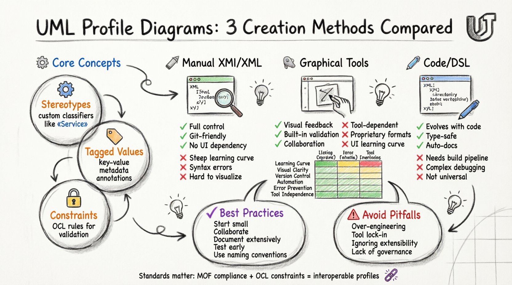
Before diving into creation methods, it is essential to understand what a Profile actually represents. A UML Profile extends the core metamodel to accommodate domain-specific concepts. It operates through a set of stereotypes, which classify model elements in new ways. It also utilizes tagged values to store additional metadata and constraints to define rules that the model must adhere to.
- Stereotypes: These are custom classifiers that extend existing UML metaclasses. For instance, a class might be stereotyped as a “Service” or a “Database Entity”.
- Tagged Values: These allow you to attach key-value pairs to model elements, similar to annotations in programming.
- Constraints: These define semantic rules, often expressed in Object Constraint Language (OCL), that govern the behavior or state of the profiled elements.
When you craft a Profile Diagram, you are essentially defining the vocabulary for a specific modeling context. This vocabulary must be consistent, reusable, and compatible with the broader modeling infrastructure.
🛠️ Method 1: Manual Definition via XMI/XML
The most direct method involves editing the underlying interchange format files directly. Unified Modeling Language profiles are typically stored in XML Metadata Interchange (XMI) format. This approach offers granular control but requires a deep understanding of the schema.
📝 How It Works
In this method, a developer opens the XMI file in a text editor. The structure of the file follows the MOF (Meta-Object Facility) specification. The profile definition is embedded within the XML hierarchy. The modeler manually writes the XML tags corresponding to the Profile, Package, and Classifier elements.
- Pros:
- Full control over the serialization format.
- No dependency on a graphical interface.
- Easy to integrate into version control systems (Git, SVN).
- Minimal overhead; no binary blobs.
- Cons:
- High learning curve due to XML verbosity.
- Prone to syntax errors that break the model.
- Difficult to visualize the structure without a rendering tool.
- Manual merging of changes is complex.
This method is often used in environments where automation scripts generate profiles directly from configuration files. It is suitable for teams with strong scripting capabilities who require precise control over the output format.
🖱️ Method 2: Graphical Modeling Environments
Most modelers prefer a visual interface. Graphical Modeling Environments provide a canvas where elements can be dragged, dropped, and connected. This is the most common approach for general software architecture teams.
🎨 How It Works
The tool provides a palette containing the base UML metaclasses. To create a Profile, the user typically creates a new Package and selects “Profile” as the type. Subsequently, stereotypes are added as child elements. Relationships between the profile and the metamodel are established through “Extension” lines.
- Pros:
- Intuitive visual feedback.
- Validation checks prevent structural errors (e.g., invalid relationships).
- Supports collaboration through shared models.
- Integrated with diagramming features for documentation.
- Cons:
- Dependent on the specific tool’s UI logic.
- File formats may be proprietary or binary.
- Learning curve exists for tool-specific shortcuts.
- Can become cumbersome for very large profiles.
When using a graphical environment, it is crucial to ensure that the tool adheres to the standard UML 2.x specification. Non-standard implementations can lead to interoperability issues when sharing models with other teams or tools.
📜 Method 3: Code Annotations and DSL
A modern approach involves defining profiles directly within the source code or through Domain-Specific Languages (DSL). This method aligns with the principle of “Model-First” or “Code-First” development, where the profile definition lives alongside the implementation artifacts.
⚙️ How It Works
Developers use language-specific annotations to define stereotypes. For example, a Java annotation might define a “Persistence” stereotype. A build process or an annotation processor then extracts these definitions and generates the corresponding UML Profile structure. Alternatively, a DSL can be written specifically to define the profile, which is then compiled into XMI.
- Pros:
- Profiles evolve with the code.
- Strong type checking via the compiler.
- Reduces duplication between design and implementation.
- Facilitates automated documentation generation.
- Cons:
- Requires a build pipeline or processor.
- Decoupling the visual diagram from the source can be tricky.
- Debugging the generation process can be complex.
- May not fit all modeling scenarios (e.g., legacy architecture).
This method is particularly effective for Model-Driven Architecture (MDA) projects where the transformation from model to code is a primary workflow.
⚖️ Comparison of Methods
To assist in selecting the right approach, the following table compares the primary methods based on key operational factors.
| Factor | Manual XMI | Graphical Tool | Code/DSL |
|---|---|---|---|
| Learning Curve | Steep | Moderate | Steep (Technical) |
| Visual Clarity | Low | High | Low (Requires Rendering) |
| Version Control | Excellent | Moderate | Excellent |
| Automation Potential | High | Moderate | Very High |
| Error Prevention | Low | High | High (Compiler) |
| Tool Independence | High | Low | Moderate |
🔄 Maintenance and Evolution
Once a Profile is created, it enters a lifecycle. Profiles are not static; they must evolve as requirements change. This is often the most challenging aspect of profile management.
📉 Managing Changes
- Backward Compatibility: When adding a new stereotype, ensure existing models can still load. Removing a stereotype is risky and should be handled with deprecation markers.
- Namespace Management: Profiles rely heavily on namespaces. As the profile grows, ensure that namespace collisions do not occur with other standard libraries or third-party profiles.
- Documentation: Every stereotype should have clear documentation explaining its purpose. This prevents ambiguity for future maintainers.
📂 Versioning Strategies
Versioning a Profile is similar to versioning software. You must decide whether to increment the major version when breaking changes occur. It is advisable to store profiles in a dedicated repository. This allows for:
- Tracking history of changes.
- Rolling back to previous versions if a new stereotype causes issues.
- Sharing profiles across different projects within an organization.
🔗 Interoperability and Standards
One of the primary risks in crafting a UML Profile is creating a “silo” model that cannot be read by other tools. Adherence to the standard is critical.
- MOF Compliance: Ensure the profile is compliant with the Meta-Object Facility. This ensures that the structure is recognized by any compliant tool.
- Standard Libraries: Use standard UML stereotypes (like
<<abstract>>or<<final>>) where possible. Introducing new ones only when necessary. - Import Mechanisms: Properly use the
<<import>>relationship to link your profile to the core UML metamodel. This establishes the context for the stereotypes.
Failure to follow these standards can result in models that are visually beautiful but semantically broken when imported into a different environment.
🧪 Validation and Quality Assurance
A profile is useless if it does not enforce the intended rules. Validation is the process of checking that models conform to the defined profile.
🛡️ Static Analysis
Many modeling platforms offer static analysis features. These check for:
- Unused stereotypes.
- Invalid dependencies between profile elements.
- Missing tagged values on required elements.
📏 OCL Constraints
For complex logic, Object Constraint Language (OCL) is the standard. It allows you to write expressions that must evaluate to true for the model to be valid. For example, you might define a constraint that says a “Database Table” stereotype must have a “PrimaryKey” tagged value.
🚧 Common Pitfalls
Even experienced modelers encounter issues. Being aware of common pitfalls can save significant time.
- Over-Engineering: Do not create a stereotype for every minor variation. If a pattern is common, use it. If it is rare, consider using standard UML extensions instead.
- Ignoring Extensibility: Design profiles with the expectation that they will be extended by others. Avoid hard-coding logic that should be flexible.
- Tool Lock-in: If a graphical tool stores the profile in a proprietary format, migration to another tool becomes difficult. Prefer XMI or standard formats.
- Lack of Governance: Without a governance process, multiple teams might create conflicting profiles. Establish a central authority for profile definitions.
🌐 Integration with Model Driven Architecture
Profile Diagrams play a pivotal role in Model Driven Architecture (MDA). In MDA, the platform-independent model (PIM) is transformed into a platform-specific model (PSM). Profiles define the specific transformations required for different platforms.
- Transformation Rules: Profiles can define rules that guide how a model element is transformed into code or database schema.
- Platform Specifics: A profile can encapsulate the specific constraints of a Java EE environment versus a .NET environment within the same model.
- Code Generation: Advanced generators read the profile to determine how to render code templates. This reduces the need for manual code writing.
📊 Best Practices for Implementation
To ensure success in crafting UML Profiles, consider the following recommendations.
- Start Small: Begin with a minimal set of stereotypes. Expand the profile as the domain requirements become clearer.
- Collaborate: Involve developers and architects in the design of the profile. The profile must make sense to the people using it.
- Document Extensively: Create a separate documentation file for the profile. Explain the “why” behind each stereotype, not just the “what”.
- Test Early: Apply the profile to a small, real-world model early in the process to identify issues before they scale.
- Use Naming Conventions: Adopt a consistent naming convention for stereotypes (e.g., prefixing with a domain name) to avoid conflicts.
🔮 Future Considerations
The landscape of modeling is evolving. As systems become more complex, the need for precise modeling increases. Emerging trends suggest a shift towards:
- Cloud-Native Modeling: Profiles that specifically address cloud infrastructure and microservices.
- AI-Assisted Modeling: Tools that suggest stereotypes based on code analysis.
- Real-Time Collaboration: Platforms that allow multiple modelers to edit the same profile simultaneously.
Staying updated with these trends ensures that the profiles you craft remain relevant and effective over time.
📝 Final Considerations
Selecting the right method for crafting UML Profile Diagrams depends on the specific needs of the project, the team’s technical skills, and the tools available. Whether through manual XML editing, graphical interfaces, or code annotations, the goal remains the same: to create a clear, maintainable, and semantically rich extension of the UML language.
By adhering to standards, maintaining version control, and prioritizing documentation, you can ensure that your profiles serve as a robust foundation for your system architecture. Remember that a profile is a contract between the model and the tool. Honoring this contract leads to better software design and fewer errors during implementation.