


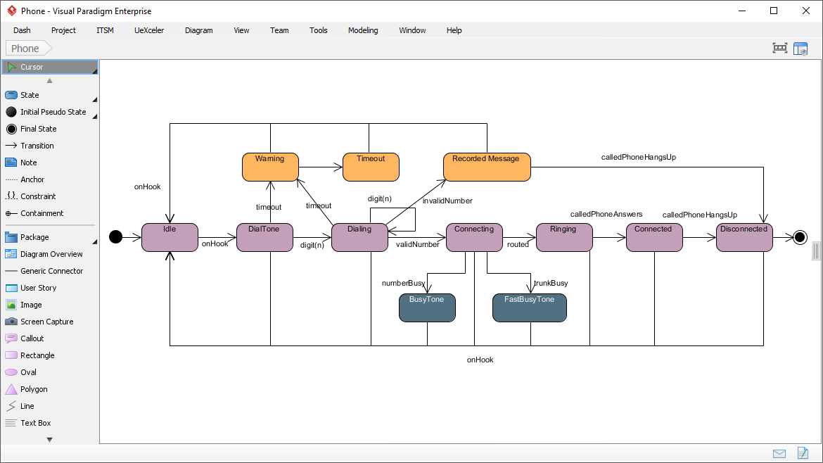
In the world of event-driven software architecture, few objects are as dynamic or state-sensitive as a telephone interface. Whether you are building a legacy PBX system, a VoIP application, or a simple dialer, understanding the lifecycle of a phone call is critical. This tutorial explores the State Machine Diagram captured in Visual Paradigm, demonstrating how to model complex interactions, error handling, and state transitions for a “Phone” object.
What is a State Machine Diagram?
A State Machine Diagram (SMD) is a behavioral UML diagram that describes the distinct states an object can exist in and the events that cause it to move from one state to another. Unlike a flowchart that shows a linear process, a state machine diagram highlights the history of an object. It answers the question: “Given that the phone is currently in the ‘Dialing’ state, what happens if the user presses ‘onHook’ versus if they enter a digit?”
Anatomy of the Phone State Diagram
The diagram provided in the screenshot maps the entire lifecycle of a phone call, starting from the moment the handset is lifted to the final disconnection. Let’s break down the key components visible in the Visual Paradigm workspace.
1. The Initial and Final States
Every state machine must have an entry point. In the diagram, you will see a solid black circle on the far left. This represents the Initial State. The arrow leading from it points to the first operational state, Idle.
Conversely, the lifecycle concludes with a concentric circle symbol (a black circle with a white center) on the far right. This represents the Final State, which is reached via the Disconnected state.
2. Core Operational States
The purple rounded rectangles represent the primary states of the Phone object. Here is the logical flow of a successful call:
- Idle: The phone is on the hook and ready to receive input.
- DialTone: Triggered when the user lifts the handset (
onHookevent). The phone generates a tone to signal readiness. - Dialing: As the user inputs digits (
digit(n)), the phone accumulates the number. If a timeout occurs here, it moves to a Warning state. - Connecting: Once the number is complete (
validNumber), the system attempts to route the call. - Ringing: The system is waiting for the recipient to answer.
- Connected: The call is live. The recipient has answered (
calledPhoneAnswers).
3. Handling Errors and Timeouts
A robust state machine must account for the “what ifs.” Notice the orange boxes in the diagram. These represent Exception States or Timeout States:
- Timeout: If the user takes too long to dial digits, the system transitions here.
- Warning: A transient state often used to alert the user (e.g., beeping) that the timer is expiring.
- Recorded Message: If the dialed number is invalid (
invalidNumber), the system may play a pre-recorded error message. - BusyTone / FastBusyTone: These blue boxes represent specific audio states triggered when the line is busy (
numberBusy) or the network is congested (trunkBusy).
Triggers and Guards
The arrows connecting these boxes are called Transitions. They are not random; they are governed by strict logic:
- Triggers: The text on the arrow (e.g.,
digit(n),onHook) is the event that causes the transition. - Guards: Sometimes an arrow has a condition in square brackets like
[validNumber]. The transition only happens if this condition is true.
For example, look at the Connecting state. It has multiple outgoing arrows:
- If
validNumberis true, it goes to Ringing. - If
numberBusyis true, it goes to BusyTone. - If
trunkBusyis true, it goes to FastBusyTone. - If
onHookoccurs, it returns to Idle.
Tooling with Visual Paradigm
This diagram was created using Visual Paradigm, a comprehensive UML modeling tool. The interface shown in the screenshot displays the standard UML palette on the left (the “Cursor” panel), allowing users to drag and drop State, State Final, and Transition elements onto the canvas.
Visual Paradigm excels at handling complex state machines because it automatically manages the layout of transitions and allows for the easy definition of entry/exit actions for states.
Defining the Logic in Code (PlantUML)
To visualize how this translates into code for other tools or documentation, here is the logic for the Dialing and Connecting states represented in a standard diagramming syntax:
@startuml
[*] --> Idle
Idle --> DialTone : onHook

DialTone --> Dialing : digit(n)
Dialing --> DialTone : onHook
Dialing --> Warning : timeout
Warning --> Dialing : timeout

Dialing --> Connecting : validNumber
Connecting --> Ringing : routed
Connecting --> BusyTone : numberBusy
Connecting --> FastBusyTone : trunkBusy

Ringing --> Connected : calledPhoneAnswers
Connected --> Disconnected : calledPhoneHangsUp
Disconnected --> [*]

@endumlConclusion
By modeling the Phone object as a state machine, developers ensure that the logic is error-free and exhaustive. The diagram clearly defines that while the phone is in the Dialing state, the only valid responses are receiving more digits, timing out, or hanging up. This level of precision is essential for building reliable event-driven systems.