


Interaction Overview Diagrams (IOD) serve as a critical bridge between high-level system requirements and detailed behavioral specifications. While introductory courses cover the linear flow from start to finish, real-world systems demand complexity. They require branching logic, parallel processes, and robust error handling. This guide explores the advanced mechanics of modeling these interactions with precision. We focus on structure, clarity, and maintainability without relying on specific tools.
When designing complex software architectures, the Interaction Overview Diagram acts as a roadmap for the control flow. It combines elements of Use Case Diagrams and Activity Diagrams to visualize how different use cases interact. Moving past simple sequences involves understanding deep control structures, managing state transitions, and ensuring the diagram remains readable as the system scales.
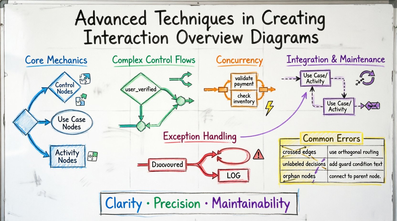
Understanding the Core Mechanics of Advanced Flows 🧩
Standard diagrams often depict a straightforward path: user action, system response, completion. Advanced modeling requires acknowledging that systems are rarely linear. They involve loops, conditional branches, and multiple entry points. To achieve this, one must understand the specific nodes available in the UML specification for IODs.
- Control Nodes: These dictate the path of execution. They include initial nodes, decision nodes, merge nodes, and final nodes.
- Use Case Nodes: Represented as ellipses, these encapsulate a specific functional unit of the system.
- Activity Nodes: Represent specific actions or sub-processes occurring within the interaction.
When transitioning from basic to advanced diagrams, the focus shifts from “what happens next” to “how does the system behave under varying conditions?” This requires a disciplined approach to node placement and connector labeling.
Structuring Complex Control Flows 🔀
Complexity in IODs often arises from conditional logic. A single decision point can lead to multiple outcomes, each requiring distinct handling. To manage this effectively, adhere to the following structural principles:
Decision Nodes and Guard Conditions
A decision node is typically represented as a diamond. It splits the flow based on boolean expressions. In advanced modeling, clarity is paramount. Do not rely on the reader to guess the condition. Every outgoing edge from a decision node must have a guard condition.
- Explicit Labeling: Label edges clearly with
trueorfalse, or specific conditions likeuser_verifiedorpayment_failed. - Completeness: Ensure all possible outcomes are covered. If a condition is not met, where does the flow go?
- Simplicity: Avoid nested decision nodes where possible. Flatten the logic to reduce cognitive load.
Merge Nodes
When multiple paths converge, a merge node is required. This signifies that regardless of the path taken, the system reaches a common state. Merging is essential for maintaining a single point of entry into subsequent processes.
- Synchronization: Ensure that all incoming flows to a merge node are logically compatible.
- State Consistency: Verify that the state of the system is consistent after the merge. Data accumulated in one branch must not conflict with data in another.
Implementing Concurrency and Parallelism ⚡
Real-world systems often execute tasks simultaneously. For example, a checkout process might validate a credit card while simultaneously checking inventory levels. Interaction Overview Diagrams can represent this through Fork and Join nodes.
Fork Nodes
A fork node splits a single control flow into multiple concurrent flows. This is visualized as a thick horizontal or vertical bar. When using fork nodes, consider the following:
- Independence: The resulting flows should ideally be independent. If they rely on shared mutable state, synchronization issues may arise in the actual implementation.
- Granularity: Ensure the tasks being forked are distinct enough to justify parallel execution.
Join Nodes
A join node waits for all incoming flows to complete before proceeding. It is the counterpart to the fork node. Proper usage prevents race conditions in the model.
- Wait Logic: The system waits for the slowest branch. If one branch completes instantly, it must hold until the other finishes.
- Data Aggregation: Consider how data from parallel branches is combined after the join. This often requires specific post-processing steps.
Exception Handling and Error Paths 🚨
Most basic diagrams ignore failure scenarios. Advanced modeling demands that error paths be explicitly defined. A system that only works when everything goes right is not robust. Documenting exceptions ensures developers understand how to handle failures.
Exception Handlers
Use specific nodes to represent exception handling blocks. These nodes trigger when a specific error condition occurs within a use case or activity.
- Categorization: Group errors by severity (e.g.,
NetworkError,ValidationError,SystemFailure). - Recovery Paths: Define whether the system can recover automatically or if it requires user intervention.
- Logging: Indicate where system logs should be generated during an exception event.
Exception Propagation
Sometimes an error in a sub-process must propagate to the parent process. Use exception edges to show this relationship. This prevents the illusion that the system has successfully completed when it has actually failed.
- Termination: Does the exception terminate the entire interaction, or just the current branch?
- Rollback: Indicate if resources acquired before the error need to be released.
Integrating with Use Case and Activity Diagrams 🔄
An Interaction Overview Diagram does not exist in a vacuum. It is part of a larger modeling ecosystem. Understanding how it relates to other diagrams ensures consistency across the documentation.
Relationship to Use Case Diagrams
Use Case Diagrams show the “what” (functional requirements), while IODs show the “how” (control flow). When creating an IOD:
- Traceability: Ensure every use case node in the IOD corresponds to a valid use case in the Use Case Diagram.
- Scope: Do not model internal logic of a use case in the IOD. Keep the IOD focused on the interaction between use cases.
Relationship to Activity Diagrams
Activity Diagrams are often used for detailed process flows within a single use case. IODs sit at a higher level. The integration strategy involves:
- Refinement: Use an Activity Diagram to expand a specific node within the IOD. This keeps the IOD clean while allowing detail where needed.
- Consistency: Ensure the initial and final nodes match between the IOD and the detailed Activity Diagrams.
Maintenance and Documentation Standards 📝
Diagrams degrade over time if not maintained. As requirements change, the diagram must evolve. Without a maintenance strategy, the IOD becomes misleading.
- Version Control: Treat diagrams as code. Track changes in version control systems.
- Naming Conventions: Use consistent naming for nodes, edges, and use cases. Avoid abbreviations that confuse stakeholders.
- Review Cycles: Schedule regular reviews of the IOD alongside code reviews. If the code changes, the diagram must reflect it.
Common Modeling Errors and Corrections 🛠️
Even experienced modelers make mistakes. The table below outlines common pitfalls in IOD creation and the strategies to correct them.
| Error Type | Impact | Correction Strategy |
|---|---|---|
| Crossed Edges | Reduces readability significantly | Use orthogonal routing or sub-nodes to route paths around conflicts. |
| Unlabeled Decision Edges | Ambiguity in logic flow | Ensure every edge leaving a decision node has a guard condition. |
| Orphan Nodes | Disconnected logic fragments | Verify every node is reachable from the initial node and can reach a final node. |
| Overly Complex Loops | Confusion regarding termination | Break complex loops into separate sub-processes or use recursion notation clearly. |
| Missing Exception Paths | False sense of security | Explicitly map out failure scenarios and recovery steps. |
Practical Application Strategies 🚀
Applying these techniques requires practice. Here are strategies to implement advanced IODs in your projects.
Iterative Refinement
Do not attempt to model the entire system in one pass. Start with the primary happy path. Once that is stable, add the branches. Finally, add the error handling. This layered approach prevents the diagram from becoming unmanageable.
Abstraction Levels
Use different levels of abstraction for different audiences.
- Executive View: High-level flow with major use cases only.
- Developer View: Detailed flow including decision nodes, loops, and exception handling.
- QA View: Focus on testable paths, including edge cases and error conditions.
Standardization
Establish a team standard for how specific elements are drawn. For example, define a standard color or shape for exception nodes. This reduces the time required to interpret the diagram for new team members.
Future-Proofing Your Models 🌐
Software requirements change. Technologies evolve. An Interaction Overview Diagram should be flexible enough to accommodate these shifts without requiring a complete redraw.
- Modularity: Design diagrams so that sections can be swapped out. If a payment provider changes, the payment interaction node should be replaceable without affecting the rest of the flow.
- Scalability: Ensure the diagram can handle an increase in use cases. Avoid cramming too many elements into a single page. Use swimlanes or grouping mechanisms if available in your notation standard.
- Clarity over Completeness: It is better to have a clear diagram that misses a minor edge case than a messy diagram that tries to show everything. Document minor edge cases in accompanying text if necessary.
Conclusion on Modeling Excellence ✨
Advanced Interaction Overview Diagrams are not just drawings; they are precise specifications. They communicate the intent of the system logic to developers, testers, and stakeholders. By focusing on control structures, concurrency, and error handling, you create a model that stands the test of time. The goal is clarity and precision, ensuring that the visual representation matches the actual system behavior. Continuous refinement and adherence to standards will keep your documentation valuable throughout the lifecycle of the project.
Remember that the diagram is a tool for communication. If the team cannot understand it, it fails its primary purpose. Prioritize readability, use standard notation, and maintain the model rigorously. This approach ensures that the Interaction Overview Diagram remains a reliable asset for your engineering efforts.
As you continue to develop your skills in UML modeling, keep these advanced techniques in mind. They form the backbone of robust system design. Apply them consistently to build systems that are not only functional but also well-documented and maintainable.