


Designing complex software systems requires precise documentation. When the architecture involves multiple components communicating over time, standard static diagrams often fall short. This is where the Interaction Overview Diagram (IOD) becomes essential. It bridges the gap between high-level workflow and detailed message exchange. However, even experienced architects stumble when modeling these dynamic flows. Errors in an IOD can lead to significant rework during the implementation and testing phases.
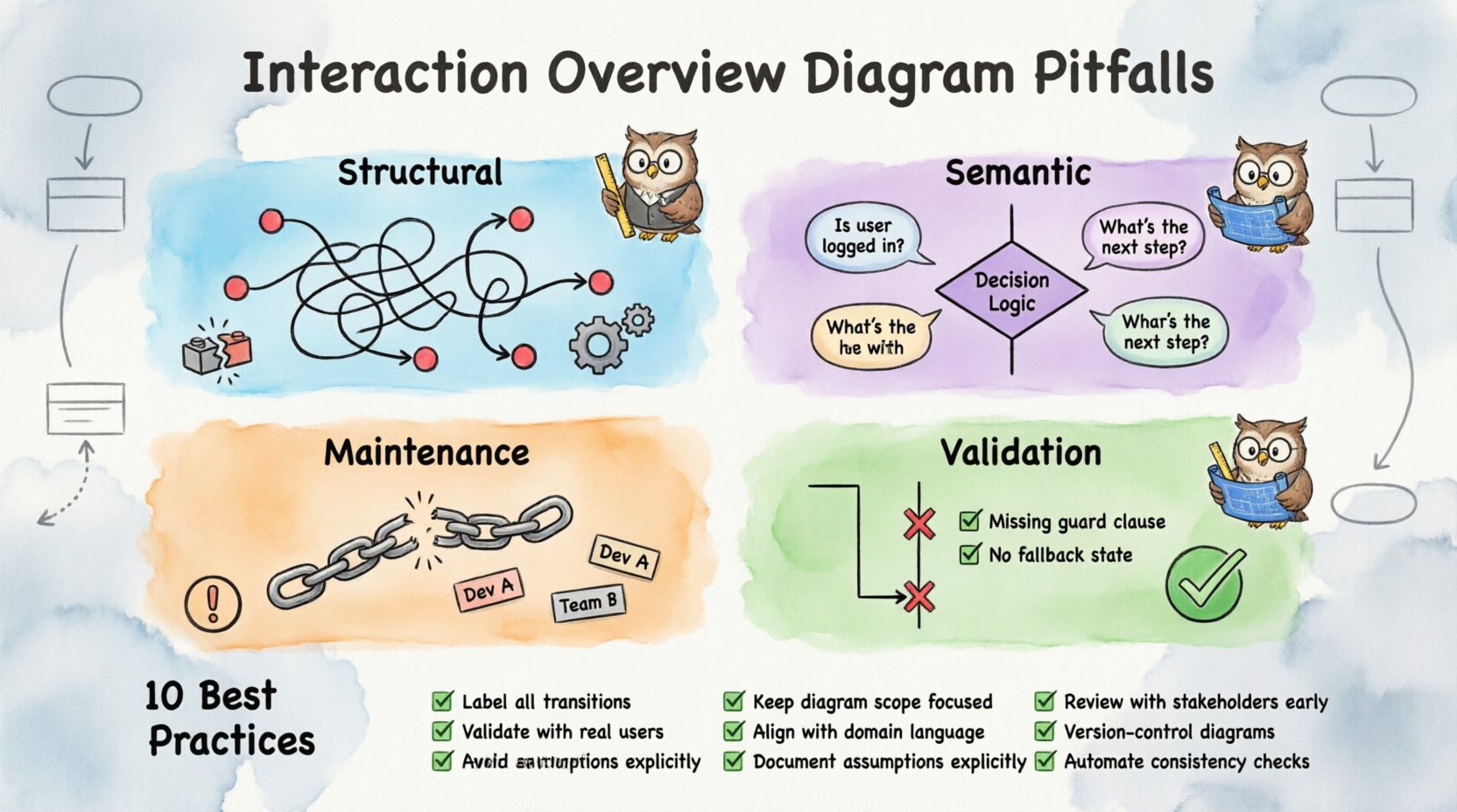
This guide addresses the structural, semantic, and maintenance pitfalls frequently encountered when creating Interaction Overview Diagrams. By understanding these common errors, you can build diagrams that serve as reliable blueprints rather than confusing artifacts. We will explore specific scenarios, analyze the consequences of mistakes, and provide actionable strategies to ensure clarity and accuracy in your system modeling.
Understanding the Interaction Overview Diagram 📐
Before diving into errors, it is necessary to define the tool. An Interaction Overview Diagram is a behavior diagram in the Unified Modeling Language (UML). It combines elements of activity diagrams with interaction diagrams, such as Sequence or Communication diagrams. The primary purpose is to control the flow of interactions between different parts of a system.
- Activity Nodes: Represent control flow steps, such as decision points or branches.
- Interaction Frames: Encapsulate specific interaction diagrams (Sequence or Communication) within the overview.
- Control Flow Edges: Connect nodes to show the order of execution.
- Object Lifelines: Show the existence of objects within the interaction frames.
When these elements are combined incorrectly, the diagram loses its ability to communicate intent. The following sections detail the specific areas where confusion typically arises.
Structural Pitfalls: Layout and Flow Control 🔄
The most immediate issues often appear in the visual layout and the logic of the flow control. A diagram that looks messy usually implies a logical mess.
1. Overlapping Control Flow Lines
One of the most frequent visual errors is allowing control flow edges to cross over interaction frames or other nodes without clear entry or exit points. While UML allows crossing lines, excessive crossing creates ambiguity about which path the system takes.
- The Mistake: Drawing a line that enters an interaction frame from the middle, rather than through a defined edge.
- The Consequence: Developers cannot determine if the interaction is optional or mandatory at that specific point in the flow.
- The Fix: Use distinct entry and exit points for every interaction frame. Ensure all lines connect to specific nodes, not the frame boundary itself.
2. Ignoring Initial and Final Nodes
Every valid IOD must have a clear starting point and a clear ending point. Missing these nodes is a critical structural flaw.
- The Mistake: Starting a flow from a decision node or ending a flow without a final activity node.
- The Consequence: The system state becomes undefined. It is unclear where the process begins or how it terminates, leading to potential infinite loops or unhandled states in code.
- The Fix: Always place a solid black circle for the initial node and a double-concentric circle for the final node. Ensure every branch eventually converges to a final node.
3. Mixing Granularity Levels
Consistency in detail is vital. An IOD should not mix high-level business logic with low-level data manipulation in the same visual plane without separation.
- The Mistake: Placing a single activity node that contains the logic for an entire subsystem, while another node only handles a single API call.
- The Consequence: The diagram becomes unreadable. Stakeholders cannot see the high-level process, and developers cannot find the specific technical details they need.
- The Fix: Adopt a standard granularity rule. For example, every node should represent a logical step in the business process, not a single line of code. Use nested interaction frames for the low-level details.
Semantic Pitfalls: Meaning and Data Flow 🧠
Visual accuracy is not enough. The diagram must also accurately reflect the data and state changes occurring within the system. This is where semantic errors creep in.
4. Failing to Pass Parameters
Interaction Overview Diagrams describe how things happen, but they often imply what data is moving. Omitting parameter details breaks the link between the diagram and the implementation.
- The Mistake: Showing an interaction frame where an object sends a message, but not specifying the arguments passed.
- The Consequence: Implementation teams must guess the input requirements. This leads to API mismatches and validation errors during integration testing.
- The Fix: Explicitly label message transitions with parameter names and types. If data flows between activity nodes, represent this using object nodes and pins.
5. Confusing Object Lifelines with Participants
There is a subtle distinction between the participants in an activity diagram and the lifelines in an interaction diagram. Mixing these roles causes confusion about ownership.
- The Mistake: Treating an object in a Sequence diagram as a passive actor in the Activity diagram without defining its role in the control flow.
- The Consequence: It becomes unclear if the object initiates an action or reacts to one. This impacts the design of event listeners and callbacks.
- The Fix: Clearly distinguish between the control flow (who decides what happens) and the interaction flow (who talks to whom). Use separate swimlanes or distinct visual cues for decision-makers versus message receivers.
6. Misusing Decision and Merge Nodes
Decision nodes (diamonds) and merge nodes are fundamental to control flow. Using them incorrectly distorts the logic.
- The Mistake: Using a decision node to split flow without assigning guard conditions to the outgoing edges.
- The Consequence: The path taken is ambiguous. If the condition is not met, the system halts or enters an undefined state.
- The Fix: Label every outgoing edge from a decision node with a boolean expression (e.g., [is_valid], [error_occurred]). Ensure merge nodes have a unique label indicating the convergence of specific paths.
Maintenance and Consistency Pitfalls 📉
A diagram is a living document. If it cannot be maintained, it becomes obsolete quickly. Several pitfalls relate to how the diagram evolves alongside the codebase.
7. Lack of Traceability
There should be a direct line of sight between the IOD and other artifacts, such as use cases, class diagrams, or user stories.
- The Mistake: Creating an IOD in isolation without referencing the source requirements or the class structure.
- The Consequence: When requirements change, the diagram is not updated. It no longer reflects reality, leading to technical debt.
- The Fix: Include references to requirement IDs or use case names in the header or within the nodes. Regularly review the diagram against the codebase during sprint reviews.
8. Inconsistent Naming Conventions
Names carry meaning. If a node is named “Process Data” in one section and “Handle Input” in another, the reader must pause to decipher if they are the same.
- The Mistake: Using synonyms for the same action across different parts of the diagram.
- The Consequence: Cognitive load increases. Developers waste time verifying if two nodes perform identical functions.
- The Fix: Establish a naming standard before starting. Use verbs for actions and nouns for entities. Review the diagram for duplicate concepts with different names.
Validation Pitfalls: Testing the Model 🧪
Creating the diagram is only half the battle. Validating that it actually works as a model is often overlooked.
9. Skipping Walkthroughs
A diagram that no one reads is useless. Skipping the walkthrough session with the team is a major pitfall.
- The Mistake: Finalizing the diagram and pushing it to the repository without a review meeting.
- The Consequence: Misunderstandings persist until the coding phase, where they are expensive to fix.
- The Fix: Schedule a review session where team members trace the flow on the diagram. Ask them to identify potential edge cases or dead ends.
10. Ignoring Exception Paths
Happy paths are easy to model. Unhappy paths (errors, timeouts, retries) are often forgotten.
- The Mistake: Designing the flow only for successful transactions.
- The Consequence: The system crashes when real-world errors occur. Robustness is compromised.
- The Fix: Dedicate specific branches to error handling. Show how the system recovers or fails gracefully. Include timeout loops and retry mechanisms in the flow.
Summary of Common Errors and Remedies
The following table summarizes the critical pitfalls discussed above, along with their impact and recommended solutions.
| Pitfall Category | Specific Issue | Impact | Recommended Solution |
|---|---|---|---|
| Structural | Overlapping Control Flow Lines | Path ambiguity | Use distinct entry/exit points for frames |
| Structural | Missing Initial/Final Nodes | Undefined state start/end | Always define start and end circles |
| Structural | Mixing Granularity Levels | Readability issues | Standardize node detail depth |
| Semantic | Failing to Pass Parameters | API mismatches | Label messages with arguments |
| Semantic | Confusing Lifelines vs Participants | Ownership confusion | Distinguish control vs interaction roles |
| Maintenance | Lack of Traceability | Outdated documentation | Link to requirements and code |
| Maintenance | Inconsistent Naming | High cognitive load | Enforce naming standards |
| Validation | Ignoring Exception Paths | System instability | Model error recovery flows |
Best Practices Checklist for IOD Creation ✅
To ensure your Interaction Overview Diagrams remain accurate and useful, follow this checklist during the design process.
- Define Scope: Clearly state what system boundary this diagram covers.
- Identify Actors: List all external entities and internal components involved.
- Map Control Flow: Ensure every path leads to a termination state.
- Label Transitions: Add guard conditions to all decision branches.
- Specify Data: Include parameter details on message interactions.
- Check Consistency: Verify naming conventions against other diagrams.
- Review Exceptions: Document how the system handles failures.
- Validate with Team: Conduct a walkthrough with developers and testers.
- Version Control: Track changes to the diagram alongside code changes.
- Keep it Simple: Remove unnecessary decorative elements that add no value.
Integrating IODs with Other Modeling Techniques 🔗
An Interaction Overview Diagram rarely exists in a vacuum. It must integrate with Class Diagrams, Use Case Diagrams, and Activity Diagrams. The following points highlight common integration errors.
Class Diagram Alignment
Ensure the classes mentioned in the IOD match the attributes and methods defined in the Class Diagram. If an interaction requires a method that does not exist in the class model, the diagram is misleading. Always cross-reference method signatures.
Use Case Alignment
Use Cases describe what the system does from a user perspective. IODs describe how the system does it technically. If an IOD omits a step required by a Use Case, the requirement is not met. Map each interaction frame to a specific Use Case or portion thereof.
State Machine Integration
For systems with complex state logic, IODs should align with State Machine Diagrams. Ensure that the control flow in the IOD respects the valid state transitions. Entering an interaction when an object is in an invalid state is a common logic error.
Final Thoughts on Diagram Quality 📝
The quality of an Interaction Overview Diagram is a direct reflection of the quality of the system design. A well-crafted IOD reduces ambiguity, accelerates development, and minimizes defects. By avoiding the pitfalls outlined in this guide, you ensure that your diagrams remain valid assets throughout the software lifecycle.
Focus on clarity over complexity. A simple diagram that is understood by everyone is more valuable than a complex one that confuses the team. Regular maintenance and strict adherence to modeling standards will keep your documentation effective. Remember, the goal is communication, not decoration.
When you encounter a complex interaction flow, pause and consider if an IOD is the right tool. Sometimes a Sequence Diagram or a simple Activity Diagram is more appropriate. Using the right model for the right context is the ultimate sign of a mature architect. Continue to refine your skills, review your diagrams, and keep the focus on the end-user experience.