


In complex software architecture and systems engineering, clarity is paramount. Models serve as the blueprint for development, yet standard Unified Modeling Language (UML) diagrams often lack the specificity required to enforce rigorous business rules or technical limitations. This is where UML Profile Diagrams become essential. They allow architects to extend the language itself, tailoring it to specific domains. A critical component of this extension is the ability to visualize constraints. By embedding rules directly into the model, teams ensure that design decisions align with predefined standards from the outset.
This guide explores the mechanics of visualizing constraints using UML Profiles. It covers the theoretical underpinnings, practical implementation strategies, and the specific syntax used to define limitations without relying on external tools. The focus remains on the structural integrity of the model and the clarity it provides to stakeholders.
Understanding UML Profiles 🧩
A UML Profile is a mechanism for customizing the UML language. It is a lightweight extension that allows users to define new concepts without modifying the core UML metamodel. Think of a profile as a specialized dialect of UML tailored for a specific industry, such as aerospace, finance, or embedded systems.
Key Components of a Profile
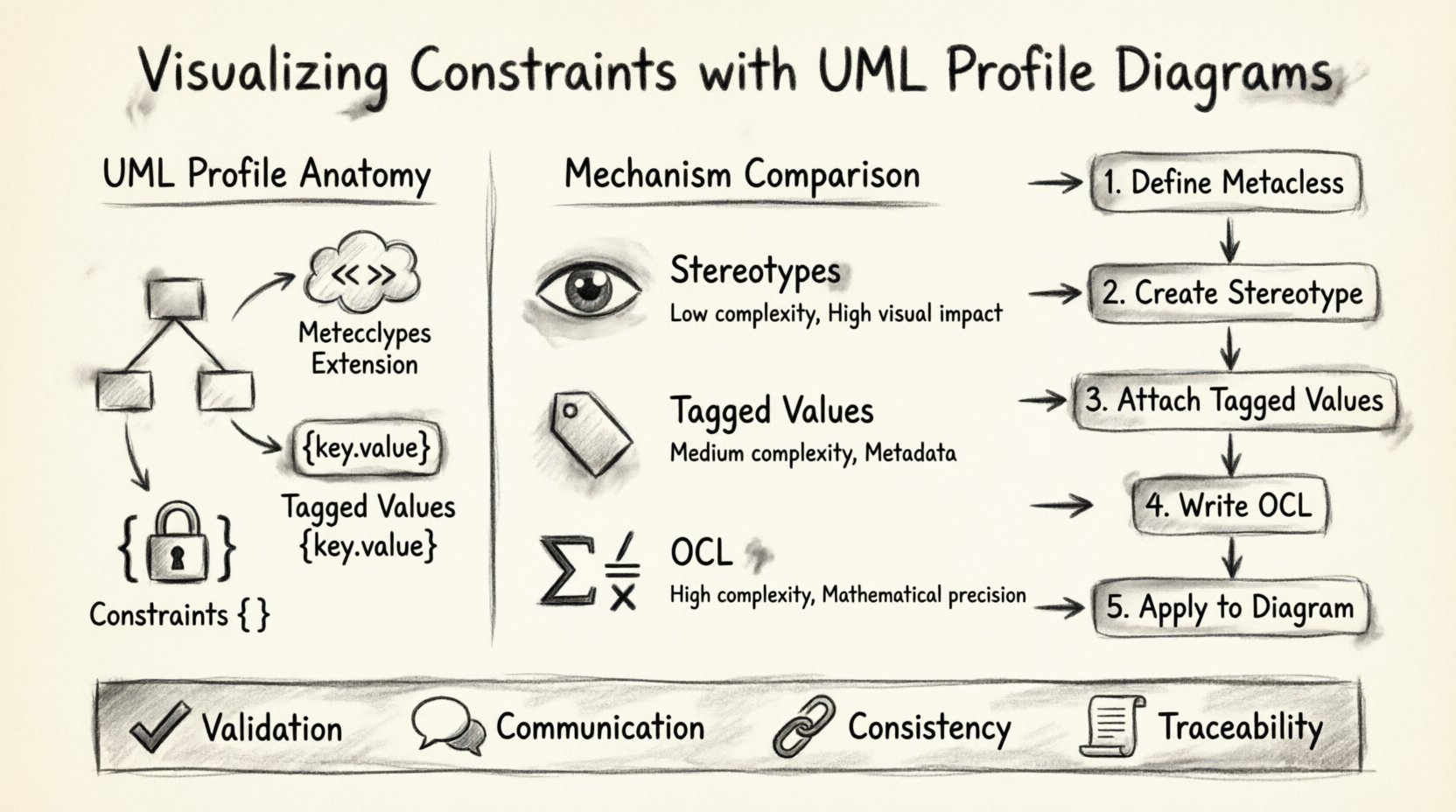
To understand how constraints fit in, one must understand the anatomy of a profile:
- Metaclass Extension: A profile links to specific UML metaclasses (e.g., Class, Association, Use Case). This tells the modeling environment which elements can be extended.
- Stereotypes: These are the visual markers added to model elements. They indicate that an element belongs to a specific domain category (e.g., <<Service>>, <<Database>>).
- Tagged Values: These are key-value pairs attached to stereotypes. They provide additional data attributes that are not part of the standard UML definition.
- Constraints: The logical rules that define valid states or behaviors for the extended elements.
Without profiles, UML remains a general-purpose language. With profiles, it becomes a domain-specific modeling language (DSML). This distinction is crucial when visualizing constraints because it moves rules from documentation (which is often ignored) into the model itself (where they are enforced).
The Role of Constraints in Modeling 🛑
Constraints are the guardrails of system design. They define what is permissible and what is prohibited. In a standard class diagram, you might define a relationship, but you cannot easily express that a relationship must exist exactly once, or that a certain attribute must be unique.
Why Visualize Constraints?
Placing constraints within the diagram serves several critical functions:
- Validation: Automated tools can check the model against these rules before code generation begins.
- Communication: Stakeholders see the rules visually, reducing ambiguity in requirements.
- Consistency: It prevents developers from implementing logic that violates the architectural intent.
- Traceability: Constraints link back to specific business requirements, creating a clear audit trail.
When constraints are hidden in text documents, they are easily overlooked. When they are part of the profile, they are part of the structure.
Mechanisms for Constraint Visualization ⚙️
There are three primary mechanisms for expressing constraints within a UML Profile. Each has strengths depending on the complexity and the target audience of the model.
1. Stereotypes as Constraints
Stereotypes are the most visual method. By creating a stereotype that implies a constraint, you can instantly identify restricted elements.
- Usage: Apply a stereotype like <<Immutable>> to a class attribute.
- Meaning: Indicates that once set, the value cannot change.
- Benefit: Immediate visual recognition during code reviews.
2. Tagged Values for Metadata
Tagged values allow for more granular data attachment. They are ideal for storing specific constraint parameters.
- Usage: Attach a tagged value named ValidationRule to a class.
- Value: Could contain a string reference to a specific rule ID or a short expression.
- Benefit: Keeps the diagram clean while retaining access to specific rule definitions.
3. OCL (Object Constraint Language)
For complex logic, natural language or simple tags are insufficient. OCL is a formal language used to express constraints. It is declarative and does not change the state of the model.
- Usage: Define preconditions, postconditions, and invariants.
- Example:
context Customer inv: self.orders->size() <= 100 - Benefit: Mathematical precision. Eliminates ambiguity in natural language rules.
Implementing Constraints Step-by-Step 🛠️
Implementing a constraint in a profile follows a logical workflow. This process ensures that the rules are defined correctly and applied consistently across the model.
Step 1: Define the Metaclass
Identify the UML element that requires the constraint. Is it a Class? An Association? A Use Case? You must register the profile to extend the correct metaclass. This ensures the constraint only applies where it is relevant.
Step 2: Create the Stereotype
Define the name of the stereotype. Use clear, domain-specific naming conventions. Avoid generic terms like Special or Custom. Instead, use terms that describe the constraint itself, such as StrictlyTyped or Readonly.
Step 3: Attach Tagged Values
Define the properties associated with the stereotype. If a constraint requires a threshold value (e.g., MaxRetryCount), create a tagged value for it. This allows the constraint to be parameterized without writing new code.
Step 4: Write the OCL Expressions
For the logic layer, write the OCL expressions. Ensure these expressions reference valid paths within the model. A broken path renders the constraint invalid. Validate the syntax rigorously before applying the profile to the rest of the model.
Step 5: Apply to the Diagram
Finally, apply the profile to the specific elements in your diagrams. The visual markers (stereotypes) and notes (constraints) should now appear on the model elements. This is the moment of visualization.
Managing Constraint Consistency 🔄
Once constraints are defined, maintaining them is a continuous task. Models evolve, and if the constraints do not evolve with them, the model becomes obsolete.
Avoiding Drift
Model drift occurs when the implementation diverges from the model. Constraints help prevent this, but they must be maintained.
- Regular Audits: Periodically review the OCL rules to ensure they match current business logic.
- Version Control: Treat the profile definition file with the same version control rigor as application code.
- Dependency Checks: Ensure that the constraints do not rely on elements that might be removed or refactored.
Common Challenges and Pitfalls ⚠️
Even with a structured approach, visualizing constraints presents challenges. Understanding these pitfalls helps in designing more robust profiles.
Over-Constraint
Adding too many constraints can make a model unreadable. If every element has a rule attached, the diagram becomes cluttered. Prioritize constraints that are critical for safety or business logic.
Complexity in OCL
OCL is powerful but can become difficult to read if nested too deeply. Keep expressions as simple as possible. Break complex rules into smaller, reusable invariants.
Tooling Limitations
Not all modeling environments support the same level of profile customization. Ensure that the constraints you visualize are supported by the tools your team uses for validation and code generation.
Comparison of Constraint Mechanisms
The following table outlines the differences between the primary mechanisms for visualizing constraints. This helps in selecting the right approach for specific scenarios.
| Mechanism | Best For | Complexity | Visual Impact |
|---|---|---|---|
| Stereotypes | Categorization and simple flags | Low | High (Icon/Text) |
| Tagged Values | Parameterized rules and metadata | Medium | Medium (Tooltip/Note) |
| OCL | Logical invariants and mathematical rules | High | Low (Note/Text Box) |
| Notes | Informal explanations and context | Low | High (Floating Box) |
Integration with Other Diagrams 📊
Constraints are not isolated to class diagrams. They can be visualized across various UML diagram types, adding value to the entire system architecture.
Sequence Diagrams
In sequence diagrams, constraints can define the validity of message exchanges. For example, ensuring that a specific message is only sent after a response is received. This can be represented by combining a stereotype with an OCL guard on the message.
State Machine Diagrams
State machines rely heavily on triggers and guards. Constraints here ensure that a state transition only occurs if specific conditions are met. Visualizing these guards directly on the transition arrow clarifies the flow logic.
Component Diagrams
For component diagrams, constraints often relate to deployment or resource usage. Defining that a component requires a specific memory threshold or processing power can be modeled as a tagged value on the component stereotype.
Best Practices for Clarity ✅
To ensure that the visualization of constraints aids rather than hinders understanding, adhere to these best practices.
- Consistent Naming: Use the same naming convention for all stereotypes across the entire project. This reduces cognitive load for the reader.
- Layered Information: Do not put all constraints on the diagram. Use the diagram for high-level rules and link to detailed OCL specifications for complex logic.
- Color Coding: If your tooling allows, use color to indicate constraint severity. Red for critical safety constraints, blue for informational ones.
- Documentation: Maintain a profile glossary. Explain what each stereotype and tagged value means in plain language.
Real-World Scenarios 🌍
Applying these concepts in real-world contexts demonstrates their value.
Scenario 1: Financial Systems
In banking, data integrity is non-negotiable. A profile might define a stereotype <<AuditTrail>>. Any class marked with this stereotype automatically enforces a constraint that all attribute changes must be logged. The OCL invariant ensures that the log entry timestamp is valid.
Scenario 2: Embedded Systems
Embedded systems have strict memory and timing constraints. A profile could define a stereotype <<RealTime>>. This triggers a constraint that the associated method must execute within a specific time window. The tagged value stores the millisecond limit.
Scenario 3: Healthcare Data
Healthcare models must adhere to privacy regulations. A profile might include a stereotype <<PII>> (Personally Identifiable Information). The constraint ensures that this data cannot be exported to external systems unless encrypted. The visual marker on the data class immediately alerts developers to the sensitivity.
Maintenance and Evolution 🔮
As systems grow, the profiles must grow with them. A static profile becomes a liability. Regular updates to the constraint definitions ensure that the model remains a true representation of the system.
When a business rule changes, the profile must be updated first. This forces the model to reflect the new reality before the code does. This top-down approach prevents the common issue where code changes outpace the documentation.
It is also important to retire unused constraints. Cluttering a profile with deprecated rules confuses new team members. A clean profile is a maintained profile.
Summary of Key Takeaways 📝
Visualizing constraints with UML Profile Diagrams transforms abstract rules into concrete structural elements. By leveraging stereotypes, tagged values, and OCL, architects can create models that are self-documenting and self-validating.
- Profiles extend UML: They allow customization for specific domains.
- Constraints enforce rules: They move requirements into the design phase.
- OCL provides precision: It handles complex logic that natural language cannot.
- Maintenance is key: Profiles must evolve with the system.
Adopting this approach reduces the gap between design and implementation. It ensures that the final system behaves exactly as the model intended, without the need for excessive manual testing of basic structural rules. The effort invested in defining these profiles pays off in reduced defects and clearer communication among teams.