


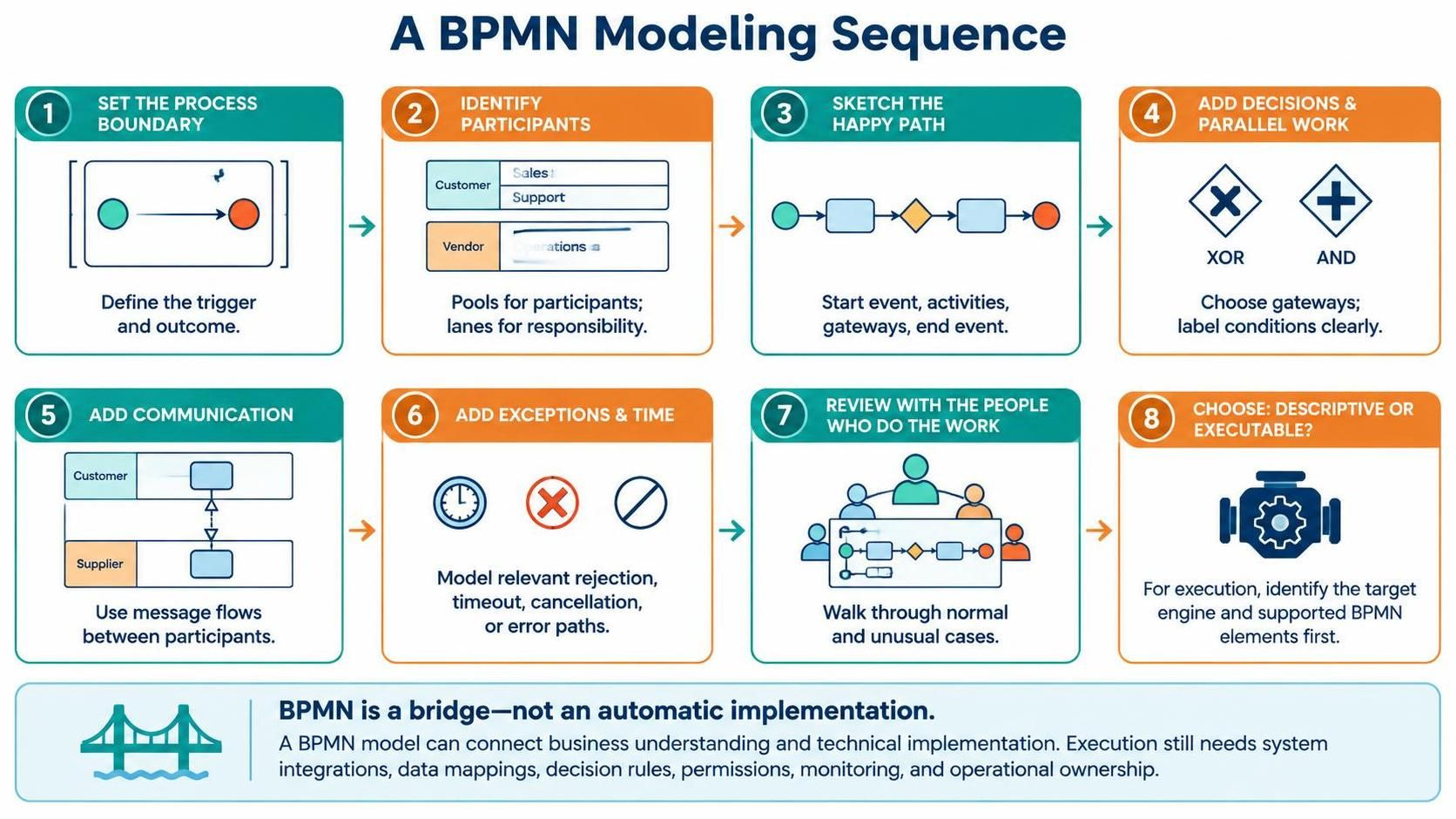
BPMN (Business Process Model and Notation) is more than just drawing boxes and arrows; it is a structured language for describing business processes. However, jumping straight into complex logic without a roadmap often leads to models that are confusing or technically unexecutable. This tutorial breaks down the 8-Step BPMN Modeling Sequence, a strategic approach to building robust process diagrams using tools like Visual Paradigm. By following this sequence, you ensure that your models are not only visually clear but also logically sound and ready for technical implementation.
Phase 1: Defining the Scope and Actors
The foundation of any BPMN model lies in clearly defining where a process begins, where it ends, and who is involved. Without these boundaries, a model can become infinite or ambiguous.
1. Set the Process Boundary
Before drawing a single activity, you must define the “Container” of your process. This involves identifying the Start Event (the trigger) and the End Event (the outcome). Ask yourself: What specific event initiates this workflow? Is it a customer placing an order, a system receiving a notification, or a scheduled time? Similarly, what defines the successful completion of the process?
2. Identify Participants
Once the boundary is set, you need to map out the stakeholders. In BPMN, Pools represent distinct participants (such as a specific organization, department, or external system), while Lanes within a pool represent specific roles or responsibilities. Organizing your diagram this way prevents “swimlane blindness,” where it becomes unclear who is responsible for a specific task.
3. Sketch the Happy Path
With the actors identified, focus on the “Happy Path”—the ideal scenario where everything goes according to plan. Start with a single thread of control using Start Event, Activities, Gateways, and End Event. Do not worry about errors or exceptions yet. This step ensures you understand the primary flow of value delivery before complicating the model with alternative paths.
Phase 2: Adding Complexity and Logic
Once the core flow is established, the next phase involves adding the intelligence and interactions that make the process realistic.
4. Add Decisions and Parallel Work
Real-world processes are rarely linear. This step introduces logic using Gateways. You must choose the appropriate gateway type to match the logic:
- XOR Gateway: Use this for exclusive decisions (e.g., “If approved, go to step A; if rejected, go to step B”).
- AND Gateway: Use this for parallel work (e.g., “Start the shipping process AND send the notification email simultaneously”).
Crucially, always label your conditions clearly to ensure the model is understandable to non-technical stakeholders.
5. Add Communication
Processes rarely happen in a vacuum. This step focuses on interactions between different participants (Pools). Use Message Flows to represent the exchange of information between pools. For example, a Customer sending an order to a Vendor is a message flow, distinct from the internal sequence flow of the Vendor processing that order.
6. Add Exceptions and Time Behavior
Now that the main flow is solid, add the “reality check.” Include relevant rejection paths, timeouts, cancellations, or error handling. You might use Timer Events to model deadlines or Error Events to model system failures. Keep this focused; adding every possible theoretical exception can clutter the diagram. Include only the paths that are critical to the business outcome.
Phase 3: Validation and Implementation Strategy
The final steps ensure the model is accurate and technically viable.
7. Review with the People Who Do the Work
A diagram is useless if it doesn’t reflect reality. Walk through the model with the actual process owners and operators. Verify that the “Happy Path” matches their daily routine and that the “Exceptions” cover the unusual cases they encounter. This walkthrough is the best way to catch logical errors and gaps in your design.
8. Decide: Descriptive or Executable?
The final decision determines the level of detail in your model. Is the diagram purely for documentation (Descriptive), or is it intended to run a workflow engine (Executable)? If you aim for execution, you must identify the target process engine and its supported BPMN elements before designing. You cannot simply draw a diagram and expect it to run; execution requires specific system calls, data mappings, and decision rules.
The Bridge to Implementation
It is vital to remember that BPMN is a bridge—not an automatic implementation. While a BPMN model connects business understanding with technical requirements, the diagram itself does not contain the code. Execution still requires system integrations, data mappings, decision rules, permissions, monitoring, and operational ownership. By following the modeling sequence above, you create a high-fidelity blueprint that makes building that technical implementation significantly faster and more accurate.