


Understanding how software components interact over time is crucial for effective system design. In the world of Unified Modeling Language (UML), the Sequence Diagram is the primary tool used to visualize this temporal flow. This tutorial serves as a comprehensive guide to understanding the anatomy of a sequence diagram, specifically focusing on the interaction between actors, lifelines, and messages.
We will deconstruct the standard elements found in Visual Paradigm to help you build robust system architectures. Whether you are a student learning the basics or a professional architect, mastering these diagrams is essential for clear communication.
1. The Core Actors and Lifelines
Every sequence diagram begins with the participants. These are the entities involved in the interaction. In our example, we see two distinct types of participants:
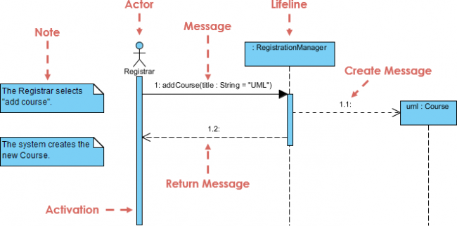
- The Actor: Represented by a stick figure, the Actor is typically an external user or a system boundary. In the diagram, we see the Registrar. This entity initiates the process by performing an action.
- The Lifeline: Represented by a vertical dashed line extending from an object box, a Lifeline represents a single instance of a class or object over time. Here, we have
:RegistrationManageranduml:Course. The vertical line signifies the existence of the object during the interaction.
The vertical axis of the diagram represents the flow of time. As you read from top to bottom, the sequence of events progresses chronologically.
2. Interactions: Messages and Activation
The heart of a sequence diagram lies in the messages exchanged between participants. Visual Paradigm offers precise control over how these messages are rendered.
Synchronous and Asynchronous Messages
Messages are depicted as horizontal arrows. The style of the arrow indicates the type of interaction:
- Synchronous Message: A solid line with a filled arrowhead (e.g.,
1: addCourse(...)). This implies that the sender waits for the receiver to complete the operation before continuing. It is a blocking call. - Return Message: A dashed line with an open arrowhead pointing back to the sender (e.g.,
1.2:). This indicates that the object is returning control or a value to the caller. - Create Message: A dashed line with an open arrowhead pointing to the target object (e.g.,
1.1). This signifies that the sender is instantiating a new object.
The Activation Bar
Notice the thin blue rectangles drawn on top of the lifelines. These are called Activation Bars (or Execution Occurrences). They indicate the period during which an object is performing an action or is actively executing a method. In the diagram, the :RegistrationManager is activated after receiving the addCourse message and remains active until it completes its tasks.
3. Annotations: Adding Context with Notes
While diagrams show the flow, they often lack specific constraints or environmental context. This is where Notes come in.
In Visual Paradigm, you can attach a Note (represented by a document icon) to any element. In our example:
- A note points to the Actor stating: “The Registrar selects ‘add course’.” This provides the trigger for the sequence.
- A second note points to the system, stating: “The system creates the new Course.” This summarizes the outcome of the internal logic.
Notes are invaluable for explaining why an action is happening or describing the state of the system without cluttering the message flow.
4. Advanced Features: Object References
Visual Paradigm allows for advanced object referencing to simplify complex diagrams. When you create a message to an object that is not visible on the screen (e.g., an object that is created later in the sequence), you can use an Object Reference.
In the diagram, notice the arrow labeled 1.1 pointing to a dashed outline of a box. This indicates that the :RegistrationManager is creating a reference to a new Course object. The object itself is not yet fully instantiated on the main timeline, but the reference is being established.
5. Best Practices for Modeling
To ensure your diagrams are readable and effective, keep these guidelines in mind:
- Keep it Chronological: Always arrange messages from top to bottom based on time.
- Group Related Messages: Use numbers (like 1, 1.1, 1.2) to group related interactions, such as a primary call and its subsequent internal steps.
- Use Clear Names: Ensure method names (like
addCourse) are descriptive and follow standard naming conventions. - Limit Scope: Do not try to model the entire system in one diagram. Focus on a specific use case or scenario.
Conclusion
Sequence diagrams are more than just technical drawings; they are a narrative tool that tells the story of how a system behaves. By combining actors, lifelines, messages, and activation bars, Visual Paradigm provides a powerful environment for modeling complex interactions. Mastering these elements will allow you to design systems that are not only functional but also well-documented and easy to understand.
%% This is a sample representation of the diagram logic for educational purposes.
%% The actual diagram was drawn using Visual Paradigm.

sequenceDiagram
    actor Registrar
    participant RM as RegistrationManager
    participant C as Course

    Note over Registrar: The Registrar selects "add course".
    Registrar->>RM: 1: addCourse(title : String = "UML")
    activate RM
    RM-->>C: 1.1: Create Course
    RM-->>C: 1.2: Initialize Course
    deactivate RM
    Note over RM: The system creates the new Course.