


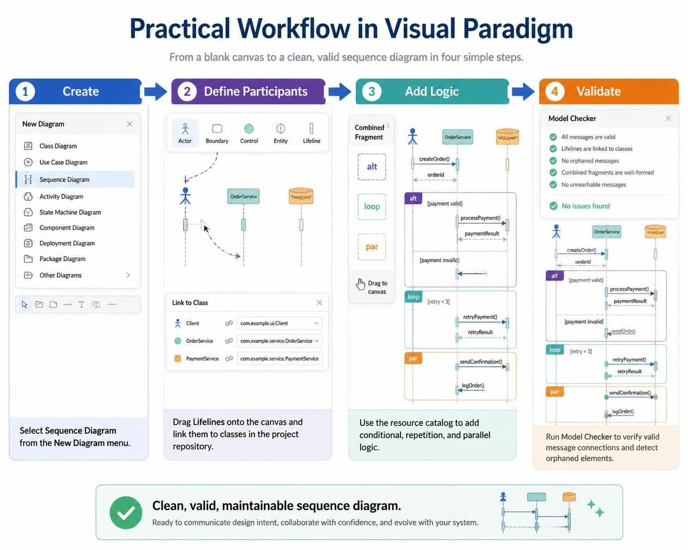
Mastering the art of interaction modeling is crucial for software architects and developers. A well-crafted Sequence Diagram not only visualizes the flow of messages between system components but also serves as a blueprint for implementation logic. In this tutorial, we will walk through the practical workflow for creating a robust sequence diagram using Visual Paradigm, ensuring your designs are clean, logically sound, and ready for collaboration.
Step 1: Create the Diagram
The process begins with setting up your workspace. Visual Paradigm offers a streamlined interface to initiate new models. Instead of navigating through complex menus, start by accessing the New Diagram menu.
- Locate the Sequence Diagram option within the list of available diagram types.
- Unlike other diagram types that might require extensive setup, the Sequence Diagram is designed for immediate interaction modeling.
Step 2: Define Participants
Once the canvas is ready, the next critical step is defining the actors and system components involved in the interaction. Visual Paradigm integrates seamlessly with your project repository to ensure consistency.
Using Lifelines
Drag Lifeline shapes onto the canvas. You will see options such as Actor, Boundary, Control, and Entity. These represent the different roles your system plays or the users interacting with it.
Linking to Classes
To maintain a strict model-driven approach, Visual Paradigm allows you to link these visual lifelines directly to your existing Java, C#, or other object-oriented classes.
- Select a lifeline (e.g., a Client or OrderService).
- Use the Link to Class dialog to bind the visual element to its code counterpart (e.g.,
com.example.ui.Client). - This ensures that if you modify the class structure later, your diagram remains synchronized.
Step 3: Add Logic with Combined Fragments
Real-world software logic is rarely linear. It involves conditions, loops, and parallel processes. Visual Paradigm simplifies the addition of this complexity through the Combined Fragment resource catalog.
Implementing Control Flow
You can drag and drop specific frames to define how messages behave:
- Alt (Alternative): Use this to model
if-elselogic. For example, a branch where a payment is either valid or invalid. - Loop: Essential for modeling iterative processes, such as a retry mechanism where a system attempts an action multiple times (
[retry < 3]). - Par (Parallel): Use this to show concurrent operations, such as sending a confirmation email while simultaneously logging the order details.
Step 4: Validate Your Model
Before finalizing your design, it is imperative to ensure logical integrity. A diagram with broken links or orphaned messages can lead to confusion during development.
Running the Model Checker
Visual Paradigm includes a powerful Model Checker tool designed specifically for sequence diagrams. By running this validation, you can verify:
- Valid Message Connections: Ensuring every message is sent to a valid receiver.
- Lifeline Integrity: Confirming that all lifelines are correctly linked to repository classes.
- Fragment Validity: Checking that alt, loop, and par frames are well-formed and have the correct activation bars.
Once the Model Checker confirms that "No issues found," you can be confident that your sequence diagram is clean, valid, and maintainable.
Conclusion
By following these four steps—Create, Define Participants, Add Logic, and Validate—you leverage the full power of Visual Paradigm to produce high-quality UML diagrams. This workflow not only speeds up the design process but also acts as a crucial quality assurance step before any code is written.