


In the world of Business Process Model and Notation (BPMN), efficiency is often the difference between a sluggish manual workflow and a streamlined, automated operation. One of the most powerful features available to process architects for achieving this efficiency is the Parallel Multi-Instance Marker. This feature allows a single task in a process diagram to automatically generate multiple concurrent instances, enabling massive scalability in operations like mass email campaigns, bulk data processing, or simultaneous quality checks.
This tutorial explores the architecture, modeling syntax, and implementation strategies for the Parallel Multi-Instance Marker, specifically leveraging the capabilities of Visual Paradigm.
Understanding the Parallel Multi-Instance Marker
The Parallel Multi-Instance Marker is a specific notation used within a Task (Activity) to indicate that the activity must be executed multiple times. Unlike a “Loop” marker, which executes the same task repeatedly until a condition is met, a Multi-Instance marker creates a collection of independent instances.
The Symbol
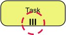
Visually, this marker is represented by three vertical parallel lines (|||) positioned at the bottom center of the activity box. This icon is the universal signal to the BPMN engine that the process logic diverges into parallel threads.
How It Works: The Architecture
When a process flow reaches a task with a Parallel Multi-Instance marker, the system performs the following architectural operations:
- Collection Evaluation: The engine evaluates a specific data expression (e.g.,
count(applicants)) to determine the number of required instances. - Instance Generation: The system instantiates the task that specific number of times. If you have 10 applicants, 10 identical “Send Invitation” tasks are created.
- Simultaneous Execution: Unlike a sequential loop, these tasks execute in parallel. The system does not wait for one to finish before starting the next.
- Independent Data Binding: Each instance is mapped to a specific item in the input collection (e.g., Instance 1 gets Applicant A, Instance 2 gets Applicant B).
Real-World Scenario: Mass Interview Scheduling
Consider a recruitment process where a hiring manager needs to send interview invitations to a shortlist of candidates. In a traditional sequential model, the system would send an email, wait for the “Send” task to finish, and then move to the next candidate. This is inefficient and delays the process.
By applying the Parallel Multi-Instance Marker:
- The process identifies a list of 5 shortlisted candidates.
- The “Send Invitations” task is triggered.
- The system instantly spawns 5 parallel threads.
- All 5 emails are dispatched simultaneously.
- The process flow only proceeds to the “Wait for Response” phase once all 5 emails have been successfully sent.
Implementation in Visual Paradigm
Visual Paradigm provides a robust environment for modeling this behavior. When using the Visual Paradigm BPMN Tool, you do not need to manually draw complex sequence flows to achieve parallelism.
Step-by-Step Configuration
- Create the Task: Drag a Task element onto your BPMN canvas.
- Apply the Marker: In the properties panel, select the “Multi-Instance” type and choose “Parallel”. The visual marker (|||) will appear automatically.
- Define the Collection: In the “Data Handling” tab, bind the task to a collection variable. For example, if you have a variable
candidates, you set the instance count expression tocount(candidates). - Map the Data: Visual Paradigm allows you to map the input variable (the collection) to the output variables. The tool automatically handles the iteration logic, ensuring that the specific data for each candidate is passed to the corresponding task instance.
Visualizing the Logic
While the diagram shows a single box, the underlying execution logic is equivalent to the following pseudo-code structure:
// Parallel Multi-Instance Logic
List candidates = getShortlistedCandidates();

// The system creates N instances of the task
for (Candidate c : candidates) {
    // Execute in parallel (asynchronously)
    sendInvitation(c);
}

// Wait for all parallel threads to complete
joinAllThreads();
Completion Lifecycle and Data Flow
A critical concept in parallel multi-instance modeling is the Completion Lifecycle. The parent activity (the overall process flow) cannot advance past the multi-instance task until a specific condition is met.
For Parallel multi-instances, the condition is simple: All instances must complete successfully. If one instance fails or is rejected, the entire batch is typically blocked until that specific instance is resolved, ensuring data integrity across the whole set.
Data Mapping and Automation
One of the most significant advantages of using Visual Paradigm for this architecture is the automation of data mapping. In manual modeling, you might struggle to define how the input list (Candidate A, B, C) maps to the output. Visual Paradigm simplifies this by allowing you to bind a collection to the marker.
The tool automatically generates the necessary iteration logic in the background. This means you can focus on the high-level business rules rather than the low-level code required to loop through arrays or lists.
Conclusion
The Parallel Multi-Instance Marker is an essential tool for modern business process automation. It transforms linear, time-consuming workflows into dynamic, parallel operations. By utilizing the BPMN features within Visual Paradigm, organizations can model, analyze, and deploy processes that scale effortlessly with the volume of work, ensuring that operations like mass communications or bulk data processing are handled with speed and precision.