


In modern software architecture, bridging the gap between high-level business requirements and technical implementation is critical. Visual Paradigm has revolutionized this workflow by integrating AI-driven diagram generation directly into its robust VPasCode editor. This tutorial explores how to leverage this powerful synergy to create, refine, and manage Use Case Diagrams with unprecedented efficiency.
This guide walks you through the architectural workflow of transforming a simple text prompt into a fully editable, syntax-perfect diagram within the VPasCode environment.
Understanding the Architecture: AI, Syntax, and Visualization
The system operates on a seamless pipeline that combines Natural Language Processing (NLP) with formal modeling syntax. The process begins not with drawing tools, but with descriptive language. The AI Chatbot is trained specifically on the syntax rules of diagramming languages (such as PlantUML) and architectural patterns.
When you interact with the chatbot, you are essentially describing a system’s functional requirements. The AI parses these descriptions and translates them into a visual representation while simultaneously generating the underlying code. This dual-output approach ensures that the diagram is both visually intuitive and technically accurate.
Step 1: Accessing the AI Chatbot Interface
The journey begins by navigating to the Visual Paradigm AI Chatbot interface. This tool is designed to understand context-specific architectural patterns. Unlike generic chatbots, this interface is specialized for software modeling.
- Input Method: Use natural language to define your system boundaries.
- Scope Definition: Clearly state the type of diagram you need, such as a “Use Case Diagram for a Food Delivery App.”
- Actor Identification: Specify the primary actors (e.g., Customer, Driver) and secondary actors (e.g., Restaurant Manager) to establish system interactions.
Step 2: The “Open in VPasCode” Integration
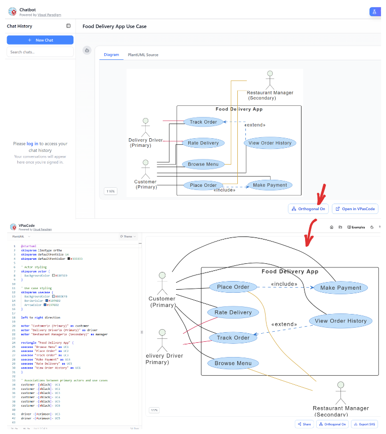
Once the AI generates the initial draft, the diagram appears with a real-time visual preview and a corresponding code panel. This is where the true power of the workflow lies: the integration with VPasCode.
Clicking the “Open in VPasCode” button serves as the critical integration point. It does not merely export an image; it transfers the complete, editable state of the diagram. The code is loaded into the editor with all syntax preserved, allowing you to switch seamlessly between visual manipulation and code editing.
Step 3: Refinement and Customization
Within VPasCode, the diagram is no longer static. You can refine the model by:
- Direct Syntax Modification: Edit the code directly to tweak specific relationships or styling parameters.
- Rendering Engine Switching: Adjust the layout algorithms to fit different aspect ratios or presentation needs.
- Iterative Conversations: Return to the chat to request changes, such as “Add error handling paths” or “Convert to a sequence diagram,” and have them instantly reflected in the editor.
Advanced Capabilities: Verification and Hierarchical Modeling
The integration offers capabilities that go beyond simple generation. It acts as an architectural assistant, capable of validating your design choices.
Automated Verification
The AI engine parses the generated diagrams to identify logical gaps. It can detect:
- Missing relationships or dependencies.
- Alternative user routes and potential edge cases.
- Architectural anti-patterns that might complicate future development.
C4 Hierarchical Modeling
For complex systems, the AI supports the C4 model, allowing you to generate multi-level documentation:
- Context Level: High-level system boundaries.
- Container Level: Application and data store relationships.
- Component Level: Internal service structures.
- Code Level: Class and interface diagrams.
Technical Deep Dive: VPasCode Syntax Structure
When you open the diagram in VPasCode, you are presented with a structured code representation. Understanding this structure is vital for advanced customization. Below is an example of the syntax generated for a food delivery application use case.
@startuml
skinparam {
    Actor {
        BackgroundColor #FFFFFF
        BorderColor #000000
    }
}

left to right direction

actor "Customer (Primary)" as customer
actor "Delivery Driver (Primary)" as driver
actor "Restaurant Manager (Secondary)" as manager

rectangle "Food Delivery App" {
    usecase "Place Order" as UC1
    usecase "Make Payment" as UC2
    usecase "Track Order" as UC3
    usecase "Rate Delivery" as UC4
    usecase "View Order History" as UC5
}

customer --> UC1
customer --> UC2
customer --> UC3
customer --> UC4
customer --> UC5

driver --> UC4
manager --> UC5

UC1 ..> UC2 : <>
UC5 ..> UC4 : <>

@enduml
This code demonstrates the separation of actor definitions, the grouping of use cases within a system boundary (rectangle), and the definition of relationships (associations, includes, and extends). In the VPasCode editor, you can modify these lines to instantly update the visual diagram.
Conclusion
The combination of AI Chatbot generation and the VPasCode editor represents a paradigm shift in software modeling. It allows architects to focus on the “what” and “why” of the system through natural language, while the tool handles the “how” of the syntax and visualization. Whether you are exporting to SVG for documentation or collaborating via shareable URLs, this workflow ensures that your diagrams are always up-to-date, accurate, and editable.