


Software architecture is often described in layers, but few tools make the transition from high-level design to low-level implementation as clear as the C4 model. While Level 1 (System Context) and Level 2 (Container) diagrams help stakeholders visualize the ecosystem, and Level 3 (Component) diagrams help developers understand service boundaries, Level 4 is where the rubber meets the road. It is the bridge between architectural intent and actual code execution.
This tutorial explores how to create and interpret C4 Level 4 Class Interaction Diagrams. These diagrams zoom in on specific code paths to map the flow of control between classes, methods, and objects. They are essential for understanding complex business logic, debugging critical paths, and documenting API behaviors.
What is a C4 Level 4 Diagram?
A Level 4 diagram is a Code Diagram. It represents the internal structure of a component—usually a specific class or a set of interacting classes—and shows how they collaborate to fulfill a specific function. Unlike a static class diagram which shows attributes and relationships, a Level 4 interaction diagram focuses on the behavior and flow.
Think of it as a sequence diagram that has been “staticized” to show the structural dependencies between classes while illustrating the dynamic flow of data.
Key Elements of the Diagram
Based on standard modeling practices (like those used in Visual Paradigm), a robust Level 4 diagram consists of three main elements:
- Class Boxes: Represent the Java/C# classes involved in the flow. Each box typically contains the class name and its public methods.
- Method Signatures: The text inside the class box (e.g.,
transfer(TransferRequest request): ResponseEntity) defines the interface. This tells the reader what the class can do. - Interaction Arrows: These lines represent method calls. They show the direction of data flow and the sequence of execution.
Decoding the “Send Money” Journey
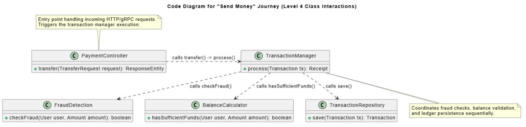
Let’s analyze the provided diagram, which maps the code flow for a financial “Send Money” feature. This is a classic example of a complex transaction flow where multiple concerns (fraud, balance, persistence) must be handled in sequence.
1. The Entry Point: PaymentController
Every request starts somewhere. In this diagram, the PaymentController is the entry point. It sits at the top, representing the class responsible for handling incoming HTTP or gRPC requests. It acts as the gateway, triggering the core logic.
2. The Orchestrator: TransactionManager
The PaymentController does not process the money itself; it delegates the work. The arrow labeled calls transfer() -> process() indicates that the controller invokes the TransactionManager. The TransactionManager is the “brain” of the operation, coordinating the various steps required to complete a transaction.
3. The Supporting Services
The TransactionManager orchestrates three distinct behaviors, represented by the boxes below it:
- FraudDetection: Checks for suspicious activity using
checkFraud(). - BalanceCalculator: Ensures the user has enough funds using
hasSufficientFunds(). - TransactionRepository: Handles data persistence using
save().
How to Create Level 4 Diagrams
Creating these diagrams manually can be tedious, but they are invaluable for documentation. You can create them using tools like Visual Paradigm or via code-based diagramming languages like PlantUML. When drawing these, ensure you capture the method signature (name and parameters) to make the diagram self-documenting.
Here is an example of how you might represent the logic of the diagram above using PlantUML syntax:
@startuml
package "Code Diagram for Send Money Journey" {
  class PaymentController {
    +transfer(TransferRequest request): Response
  }
  class TransactionManager {
    +process(Transaction tx): Receipt
  }
  class FraudDetection {
    +checkFraud(User user, Amount amount): boolean
  }
  class BalanceCalculator {
    +hasSufficientFunds(User user, Amount amount): boolean
  }
  class TransactionRepository {
    +save(Transaction tx): Transaction
  }
}

PaymentController --> TransactionManager : calls transfer() -> process()
TransactionManager --> FraudDetection : calls checkFraud()
TransactionManager --> BalanceCalculator : calls hasSufficientFunds()
TransactionManager --> TransactionRepository : calls save()

note right of PaymentController
  Entry point handling incoming HTTP/gRPC requests.
  Triggers the transaction manager execution.
end note

note right of TransactionRepository
  Coordinates fraud checks, balance validation,
  and ledger persistence sequentially.
end note
@endumlBest Practices for Level 4 Documentation
1. Focus on the “Happy Path” and Critical Flows
Do not attempt to diagram every single method in a class. Instead, focus on the specific journey or use case you are explaining. In the example above, the diagram focuses on the “Send Money” journey. If you were debugging a login issue, you would create a separate Level 4 diagram for the authentication flow.
2. Use Descriptive Notes
Arrows are good, but notes are better. The diagram includes notes explaining why a controller exists or what the repository does. These annotations add context that a developer might miss when looking at raw code.
3. Maintain the Hierarchy
Remember that a Level 4 diagram is part of a larger picture. It should never contradict the Level 3 Component diagram. If the Component diagram says PaymentService handles transfers, the Level 4 diagram should show how PaymentController interacts with TransactionManager to achieve that result.
Conclusion
Level 4 diagrams are the ultimate tool for bridging the gap between “System Design” and “Code Implementation.” By visualizing the class interactions, you reduce ambiguity, help new developers onboard faster, and create a living map of your most critical business logic. Start with your most complex service today and map out its class interactions—you’ll be amazed at how quickly your team’s understanding improves.