


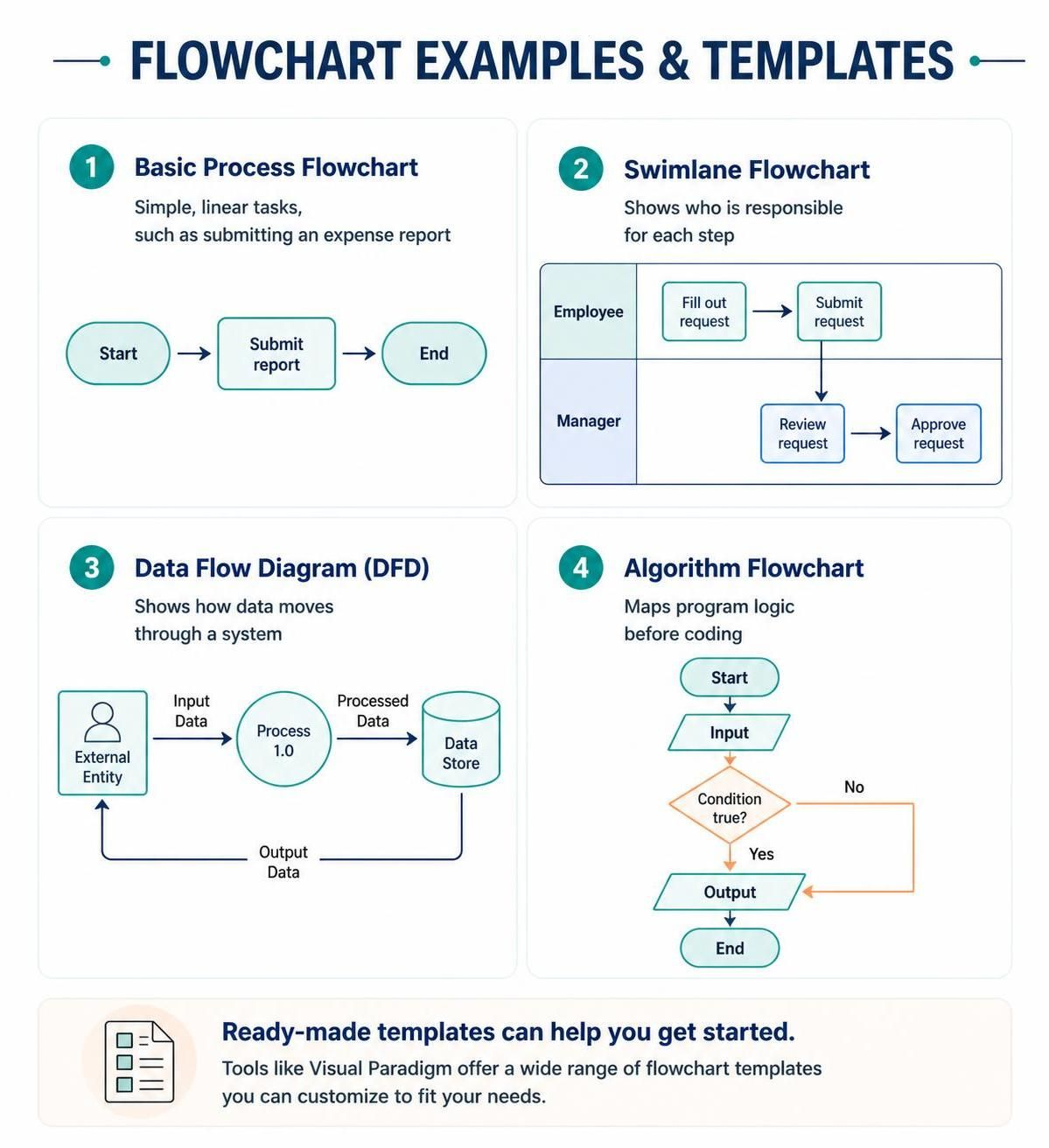
In the realm of software engineering and business process management, visualization is not merely an aesthetic choice—it is a critical component of system architecture and logic validation. Visual Paradigm, powered by its VPasCode tool and integrated AI, allows engineers to transition from abstract requirements to concrete, executable specifications.
This tutorial explores the four foundational diagram types: Basic Process Flowcharts, Swimlane Flowcharts, Data Flow Diagrams (DFD), and Algorithm Flowcharts. We will examine the architectural purpose of each, the modeling standards they adhere to, and how to implement them using code-first methodologies.
1. Basic Process Flowchart: The Linear Narrative
The Basic Process Flowchart is the most fundamental tool for documenting a linear sequence of operations. It is primarily used for Simple, Linear Tasks such as “How to Submit an Expense Report” or a standard approval workflow.
From a modeling perspective, this diagram relies on standard ANSI/ISO flowchart symbols:
- Oval/Terminal: Represents the Start and End points of the process.
- Rectangle/Process: Denotes a specific action or operation (e.g., “Submit report”).
- Arrow/Flowline: Indicates the direction of control flow.
In Visual Paradigm, this can be rapidly generated to document standard operating procedures (SOPs). When using VPasCode, a linear flow is defined by a sequential list of steps, where the output of one step becomes the input of the next.
2. Swimlane Flowchart: Cross-Functional Responsibility
While a basic flowchart shows what happens, a Swimlane Flowchart reveals who is responsible. This diagram type partitions the visual space into horizontal or vertical “lanes,” each representing a specific actor, role, or department (e.g., Employee, Manager).
Architectural Significance
Swimlanes are essential for identifying bottlenecks and handoff points in cross-functional teams. In the provided example, the “Employee” lane handles the initiation of the request, while the “Manager” lane handles the validation. The flow crosses the lane boundary only when a transfer of responsibility occurs.
Implementation Logic
When modeling this in VPasCode, the architecture is defined by assigning specific steps to specific lanes. This enforces a strict separation of concerns, ensuring that logic belonging to the “Manager” is clearly distinct from the “Employee’s” logic.
// Swimlane Logic Example
Lane: Employee
    Step: Fill out request
    Step: Submit request
    Flow: Submit request -> Manager_Lane

Lane: Manager
    Step: Review request
    Step: Approve request
    Flow: Review request -> Approve request
3. Data Flow Diagram (DFD): The Data Perspective
A Data Flow Diagram (DFD) shifts the focus from process logic to data movement. It is a standard in structured systems analysis for modeling how information enters a system, is processed, and is stored.
Core Components
- External Entity (Square): The source or destination of data outside the system (e.g., a User or another system).
- Process (Circle/Rounded Rect): A transformation of data (e.g., “Process 1.0”).
- Data Store (Open Rectangle/Cylinder): A repository where data is saved for later retrieval.
- Data Flow (Arrow): The movement of data with a specific label (e.g., “Input Data”).
DFDs are crucial for database design and API architecture. They help engineers visualize whether all required inputs are being captured and if data is being persisted correctly. In Visual Paradigm, DFDs are often used to define the scope of a system before detailed coding begins.
4. Algorithm Flowchart: The Logic Blueprint
The Algorithm Flowchart is the developer’s primary tool for mapping program logic before writing a single line of code. Unlike business process maps, these diagrams must handle complex control structures, specifically conditional branching.
Handling Branching Logic
The defining feature of an algorithm flowchart is the Decision Diamond. This shape represents a point where the program must evaluate a boolean condition (e.g., Condition true?). The flow splits into two paths:
- Yes/True Path: The code executes if the condition is met.
- No/False Path: The code skips or executes an alternative path.
In VPasCode, this logic is often represented using pseudo-code structures that map directly to if-else blocks in languages like Java, C++, or Python. This ensures that the logic is sound before the syntax is written.
// Algorithm Logic Example
Start
  Input: User_Data
  If (User_Data.Valid == true) Then
    Output: Processed_Data
  Else
    Output: Error_Message
  End If
End
Conclusion
Whether you are mapping a simple expense report or designing a complex algorithm, Visual Paradigm provides the necessary structure. By utilizing VPasCode, you can leverage AI to generate these diagrams from natural language descriptions, streamlining the transition from concept to implementation.