


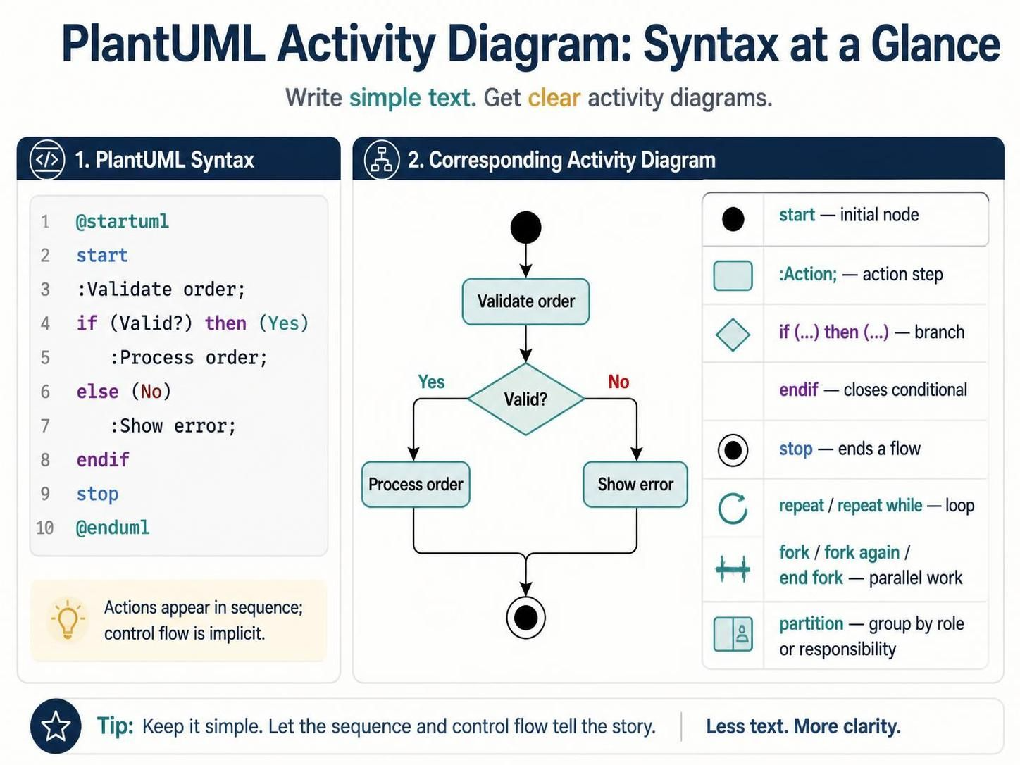
Visualizing system logic is a critical skill for developers, architects, and business analysts. PlantUML offers a powerful, text-based approach to creating these diagrams, allowing teams to generate clear, standardized charts directly from simple text descriptions. Whether you are using Visual Paradigm or the VPasCode Editor, understanding the core syntax is essential for mapping out complex workflows efficiently.
This tutorial breaks down the essential components of a PlantUML Activity Diagram, using a practical example of an order validation process to illustrate how text transforms into a visual flow.
The Anatomy of an Activity Diagram
An Activity Diagram is a type of behavior diagram in UML that describes the flow of control and data from one activity to another. In the context of text-based modeling, the diagram is wrapped in specific delimiters to indicate the start and end of the rendering process.
-
@startuml:</strong> This directive marks the beginning of the diagram definition. It tells the parser to interpret the following text as a PlantUML diagram.</li>
    <li><strong>@enduml
:
This directive marks the end of the diagram definition. It signals that the flow description is complete and ready to be rendered.
Step 1: The Initial Node
Every activity diagram must have a clear entry point. In PlantUML, this is defined using the start keyword. This creates a solid black circle, representing the initial state of the process where control flow begins.
Step 2: Defining Actions
Once the process starts, the system performs specific tasks. These are known as “actions.” In the syntax, actions are defined with a colon prefix followed by the action description and a semicolon. For example, :Validate order; creates a rectangular node representing the work being done.
A key feature of this syntax is that actions are implicitly connected. If you list two actions sequentially, the tool automatically draws a flow arrow from the first to the second. This eliminates the need for manual line drawing, streamlining the design process.
Control Flow: Branching Logic
Real-world systems rarely follow a straight line; they make decisions. PlantUML handles this logic using conditional statements.
The If/Else Statement
To introduce decision points, we use the if and else keywords. This creates a diamond-shaped decision node in the diagram. The syntax follows a structure similar to standard programming languages:
if (condition) then (label): Defines the path taken when the condition is true.else (label): Defines the alternative path taken when the condition is false.endif: Closes the conditional block.
In our example, the condition Valid? splits the flow. If the order is valid, it follows the “Yes” branch to :Process order;. If not, it follows the “No” branch to :Show error;.
Terminating the Flow
After the conditional logic is complete, the diagram must conclude. The stop keyword generates a solid black circle with a border (an “action final” node), indicating that this specific flow of control has ended.
Advanced Concepts: Parallelism and Loops
Beyond simple linear flows and branches, PlantUML supports modeling complex concurrent behaviors.
- Parallel Work: The
fork,fork again, andend forkkeywords allow you to model tasks that happen simultaneously. This is crucial for performance analysis or defining multi-threaded processes. - Loops: To model iterative processes, use
repeatorrepeat while. This creates a looping structure where an action is performed until a condition is met. - Responsibility Groups: The
partitionkeyword is used to group activities by role or responsibility (often creating “swimlanes” in the diagram), clarifying who or what is responsible for each step.
Putting It All Together: The Code
Let’s look at the complete syntax for the order validation process described in this tutorial. Notice how the text structure directly maps to the visual nodes and arrows.
@startuml
start
:Validate order;
if (Valid?) then (Yes)
  :Process order;
else (No)
  :Show error;
endif
stop
@enduml
Conclusion
By mastering these fundamental syntax rules, you can quickly prototype system architectures and process flows. Whether you are documenting a simple validation routine or designing a complex parallel workflow, PlantUML provides a concise and powerful way to communicate technical logic.