


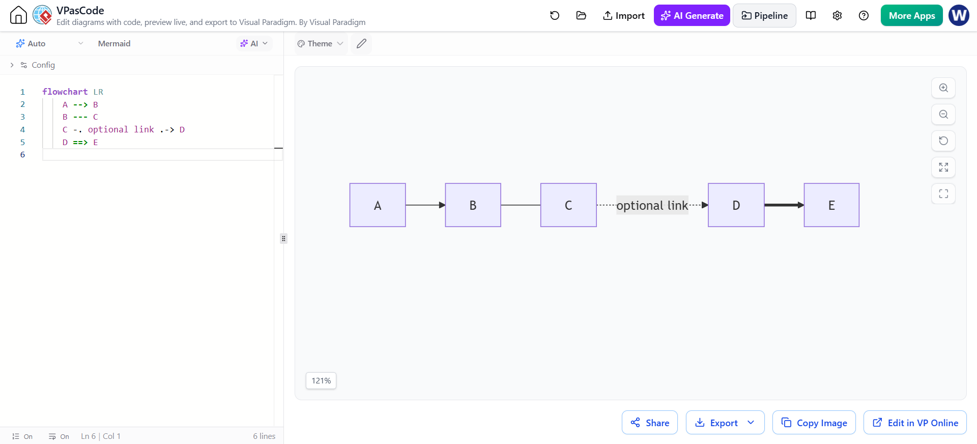
Visual Paradigm’s VPasCode Editor offers a powerful code-first approach to diagramming, allowing developers and architects to define complex system architectures using plain text. The screenshot provided showcases a classic Mermaid flowchart configuration. Unlike traditional drag-and-drop tools, this environment relies on specific syntax rules to render the visual relationships between data points. By understanding the underlying code, you can generate diagrams that are version-controllable, reproducible, and easily modifiable.
Defining the Flow Direction
The foundation of any Mermaid flowchart is the declaration of its direction. In the provided code snippet, the first line reads flowchart LR. This is a directive that sets the layout algorithm for the entire diagram.
- LR (Left to Right): This specifies that the flow of the process moves horizontally from the left side of the canvas to the right. This is the standard orientation for most linear process flows.
- Alternative Directions: You can also use
RL(Right to Left),TD(Top to Down), orBT(Bottom to Top) to suit vertical or inverted architectures.
Connecting Nodes with Syntax
The core functionality of the diagram lies in how the nodes (the boxes labeled A, B, C, D, and E) are linked. The syntax generally follows the pattern NodeID --- NodeID. However, the specific characters used between the IDs dictate the visual style of the connector. Let’s break down the specific connectors demonstrated in your screenshot:
1. The Directed Arrow (Standard Flow)
The line A --> B creates a solid line with a classic arrowhead pointing from A to B. This represents a definitive, mandatory flow of control or data. It is the most common connector used to show the primary path of a process.
2. The Undirected Link (Relationship)
The line B --- C produces a solid line without an arrowhead. This is used to indicate a relationship or association that is bidirectional or non-directional. In system architecture, this might represent a shared database connection or a non-sequential link between two components.
3. The Optional or Weak Link
The line C -. optional link .-> D demonstrates a dotted arrow. The .- syntax creates a dotted line, while the .-> creates a dotted arrow. This is frequently used to indicate optional steps, alternative paths, or weak associations where the flow is not strictly required or is conditional.
4. The Thick Arrow (Critical Path)
The final line, D ==> E, creates a thick arrow. The double equals sign == instructs the renderer to draw a heavier line. This is often used in visual design to highlight a critical path, a high-priority data transfer, or a “heavy” transaction in the system.
flowchart LR
    A --> B
    B --- C
    C -. optional link .-> D
    D ==> E
Best Practices for VPasCode Modeling
When working within the VPasCode interface, consistency is key to maintaining clean diagrams. Always ensure that your node IDs (A, B, C, etc.) are unique. While the tool is forgiving, complex diagrams with hundreds of nodes benefit from descriptive IDs (e.g., UserLogin --> AuthCheck) rather than single letters.