


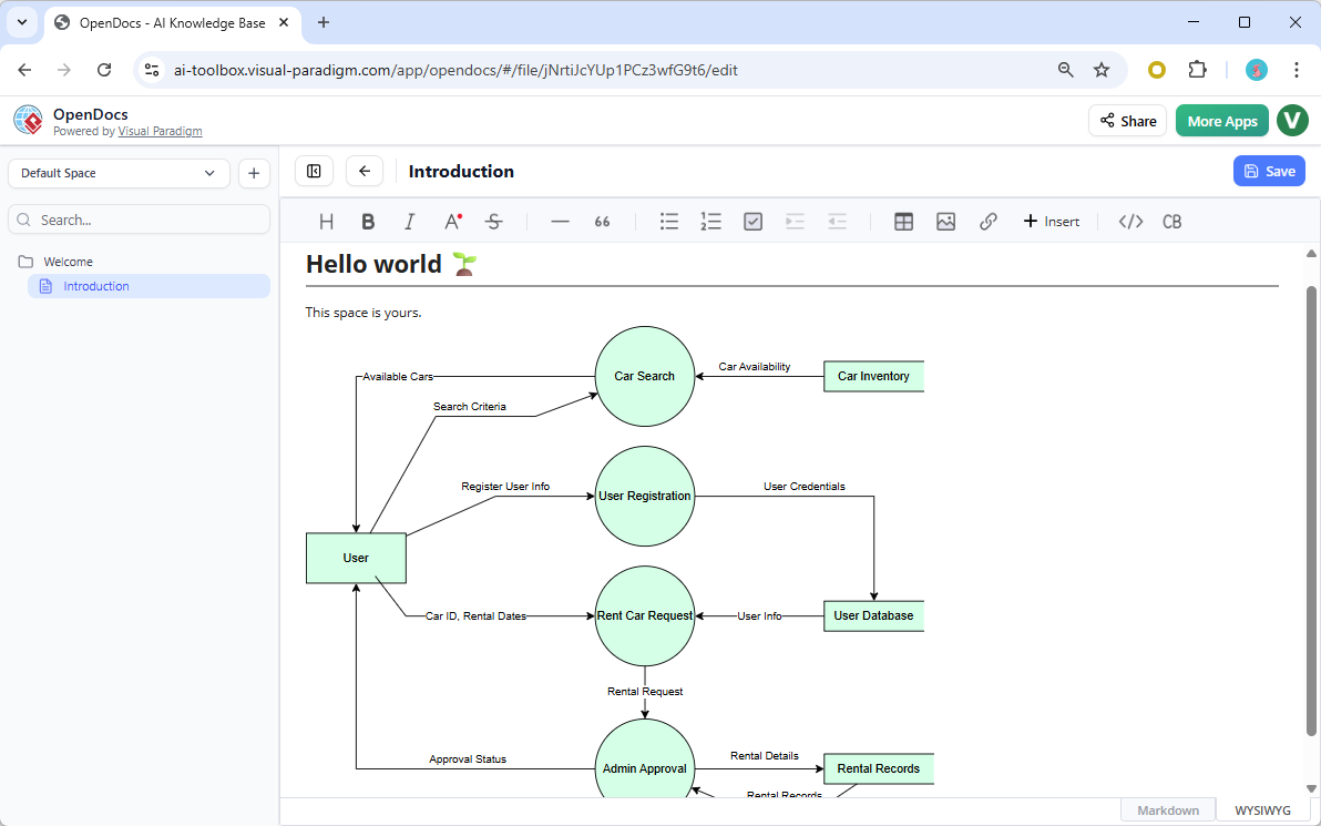
Data Flow Diagrams (DFDs) are fundamental tools in systems analysis and software engineering, providing a visual representation of how data moves through a system. When integrated into collaborative environments like OpenDocs—powered by Visual Paradigm—these diagrams become dynamic, living documents rather than static images.
In this tutorial, we will analyze a specific scenario: a Car Rental System. We will break down the diagram shown in the provided screenshot, explaining the flow of information from the initial user interaction to final administrative recording. By the end, you will understand how to structure your own DFDs for clarity and efficiency.
Understanding the Core Components
Before diving into the specific flows, let’s define the standard elements visible in this Car Rental System diagram:
- External Entities (Rectangles): These represent sources or destinations of data outside the system’s boundary. Here, the
Useracts as the primary actor initiating processes. - Processes (Circles): These represent actions or transformations that data undergoes. Examples include
Car Search,User Registration, andRent Car Request. - Data Stores (Open Rectangles): These represent places where data is held for later retrieval, such as the
Car InventoryorUser Database. - Data Flows (Arrows): These indicate the direction in which data moves, labeled with the specific data packet being transferred (e.g.,
Search Criteria).
Analyzing the Data Flow Logic
The diagram illustrates a logical progression of events. We can trace the system’s operation through three distinct phases: Search, Registration, and Rental Processing.
Phase 1: The Search Interaction
The process begins when the User entity interacts with the system. The user sends Search Criteria to the Car Search process. Simultaneously, the system queries the Car Inventory data store to check availability.
The result of this interaction is Car Availability data, which flows back from the inventory to the search process and finally to the user. This closed loop ensures the user is only presented with realistic options.
Phase 2: Identity Management
For a user to rent a car, they must be identified. The diagram shows a dedicated User Registration process. The user provides Register User Info, which the system transforms into User Credentials.
These credentials are then persisted into the User Database. This separation of the registration process from the rental process is a best practice in system design, ensuring data integrity before business logic is applied.
Phase 3: The Rental Transaction
This is the core business logic of the system. The Rent Car Request process acts as a central hub:
- The
Usersubmits Car ID and Rental Dates. - The system retrieves User Info from the
User Databaseto validate the request. - The combined data is processed, resulting in a Rental Request.
This request is then passed to the Admin Approval process. This step is crucial for business logic, allowing for human intervention or automated rule checks (e.g., credit checks) before a rental is finalized.
Architectural Insights: OpenDocs Integration
The screenshot provided demonstrates the power of embedding these diagrams directly into documentation. In OpenDocs, this isn’t just a static image; it is a live component.
By embedding the DFD, the technical team ensures that the visual model stays synchronized with the textual requirements. If the Car Search logic changes in the backend, the diagram can be updated, and the documentation reflects that change instantly. This eliminates the “documentation drift” common in traditional PDF-based modeling.
Key Takeaways for Modelers
When creating your own diagrams using this Car Rental example as a template, remember the following principles:
- Maintain Data Integrity: Always ensure that a process has an input before it produces an output. The
Rent Car Requestprocess correctly waits for both user input and database validation before proceeding. - Label Flows Clearly: Notice how every arrow has a descriptive label. Never leave a data flow unlabelled; it must represent a tangible piece of information (e.g., “Approval Status”, not just “Status”).
- Decompose Complex Processes: If
Admin Approvalbecomes too complex, it can be “exploded” into a Level 1 DFD, breaking down the approval into sub-processes like “Check Credit” and “Verify Insurance.”
By mastering these structures, you can effectively communicate complex system architectures to both technical and non-technical stakeholders.