


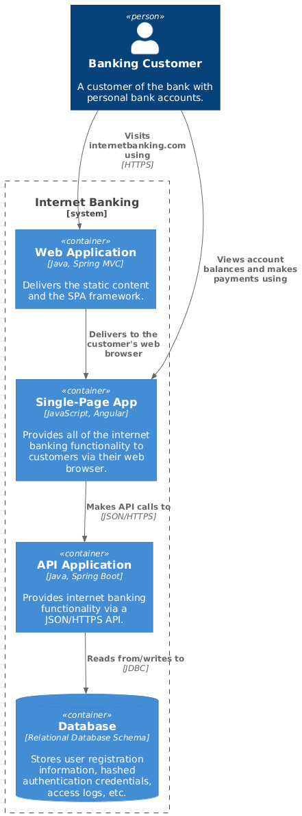
In the world of software architecture, clarity is currency. As systems grow in complexity, abstracting them into understandable models becomes the primary challenge for architects and developers. This tutorial explores Level 2: Container Diagrams within the C4 model framework. We will dissect a real-world example of an Internet Banking System, analyzing how deployable units, technology stacks, and data flows interact to deliver a secure user experience.
Understanding the C4 Model Context
Before diving into the code, it is essential to understand where we are in the architectural hierarchy. The C4 model (Context, Container, Component, Code) is a hierarchical approach to software architecture documentation. This specific diagram represents Level 2, which zooms into a specific system to reveal its internal structure.
At this level, we stop worrying about high-level business goals and start focusing on the “building blocks” of the software. We identify Containers—standalone, deployable units such as web applications, mobile apps, or microservices. We also map the relationships between these containers and how they interact with the outside world.
Analyzing the Architecture: The Banking Example
The diagram we are analyzing depicts a classic, yet robust, architecture for a banking platform. It moves beyond a simple monolith, adopting a pattern where the frontend is decoupled from the backend logic.
1. The Actor: Banking Customer
Every interaction begins with the Person element. In this model, we define a Banking Customer. This is not just a generic user; the description specifies they have personal bank accounts. This distinction is crucial for security modeling, as it implies the need for authentication and role-based access control (RBAC).
2. The System Boundary: Internet Banking
We encapsulate the entire solution within a System Boundary labeled “Internet Banking.” This boundary acts as a logical container, grouping all the internal components that belong to this specific product line. It defines the scope: anything inside is part of the internet banking system, and anything outside is an external dependency.
3. The Containers
Inside the boundary, we find four distinct containers. Let’s break down their roles and technologies:
- Web Application (Java, Spring MVC): This container serves a critical gatekeeping role. It delivers static content and the initial Single-Page Application (SPA) framework. It acts as the entry point for the user’s browser.
- Single-Page App (JavaScript, Angular): This is the client-side logic. Unlike traditional server-side rendering where the server sends a new HTML page for every click, this container runs entirely in the browser. It handles the UI interactivity, such as viewing balances and initiating payments.
- API Application (Java, Spring Boot): This is the backbone of the system. It exposes a JSON/HTTPS API. It acts as the gateway to the core banking logic, ensuring that the frontend remains “dumb” and only focuses on presentation.
- Database (Relational Database Schema): The persistent storage layer. It stores user registration data, hashed credentials (crucial for security), and access logs.
Mapping the Data Flows
Architecture is not just about static boxes; it is about the movement of data. The relationships in the diagram tell the story of a secure transaction:
- HTTPS Handshake: The customer connects to the Web Application via
HTTPS. This encryption layer is non-negotiable in banking to protect sensitive data in transit. - Client-Side Execution: The Web Application delivers the SPA. The customer then interacts with the Single-Page App. This connection is logical (the user sees it), but technically, the heavy lifting happens on the client.
- API Interaction: When the user performs an action (like checking a balance), the SPA makes an asynchronous
JSON/HTTPScall to the API Application. This decoupling allows the frontend and backend teams to work independently. - Persistence: Finally, the API Application reads from and writes to the Database using
JDBC(Java Database Connectivity). This ensures that user state is preserved across sessions.
Visualizing the Architecture with PlantUML
To replicate this architecture or adapt it for your own projects, we use the C4-PlantUML syntax. This declarative language allows you to describe your architecture in text, which is then rendered into a diagram.
Below is the complete code snippet used to generate the diagram above. It demonstrates how to define the system boundary, the containers, and the specific technology stacks associated with each component.
@startuml
!include https://raw.githubusercontent.com/plantuml-stdlib/C4-Container/master/C4_Container.puml

Person(customer, "Banking Customer", "A customer of the bank with personal bank accounts.")

System_Boundary(c1, "Internet Banking") {
    Container(web_app, "Web Application", "Java, Spring MVC", "Delivers the static content and the SPA framework.")
    Container(spa, "Single-Page App", "JavaScript, Angular", "Provides all of the internet banking functionality to customers via their web browser.")
    Container(api, "API Application", "Java, Spring Boot", "Provides internet banking functionality via a JSON/HTTPS API.")
    ContainerDb(db, "Database", "Relational Database Schema", "Stores user registration information, hashed authentication credentials, access logs, etc.")
}

Rel(customer, web_app, "Visits internetbanking.com using", "HTTPS")
Rel(customer, spa, "Views account balances and makes payments using")
Rel(web_app, spa, "Delivers to the customer's web browser")
Rel(spa, api, "Makes API calls to", "JSON/HTTPS")
Rel(api, db, "Reads from/writes to", "JDBC")
@enduml
Key Takeaways
This diagram effectively communicates the separation of concerns within the system. By explicitly stating the technologies (e.g., Angular, Spring Boot, JDBC), we provide immediate context for developers looking to maintain or extend the system. The flow clearly delineates the responsibility of the client (Angular) versus the server (Spring Boot), preventing architectural drift.