


In the modern software development lifecycle, the gap between a high-level business requirement and a detailed technical implementation is often bridged by the tedious task of manual diagramming. Visual Paradigm is revolutionizing this workflow by integrating Generative AI directly into its core engine. This tutorial explores how to leverage the AI Diagram Generation tool to transform a simple natural language prompt into a fully realized, standards-compliant UML Class Diagram, accelerating your architectural refinement process.
Understanding the AI Modeling Workflow
The traditional approach to system modeling involves selecting specific tools, defining classes, drawing relationships, and ensuring syntax adherence. Visual Paradigm’s AI ecosystem replaces this manual labor with a prompt-driven engine. By embedding AI into the interface, the software interprets user intent and automatically constructs complex structural models. This allows engineers to focus on design decisions rather than structural heavy lifting.
Step 1: Initiating the Generation
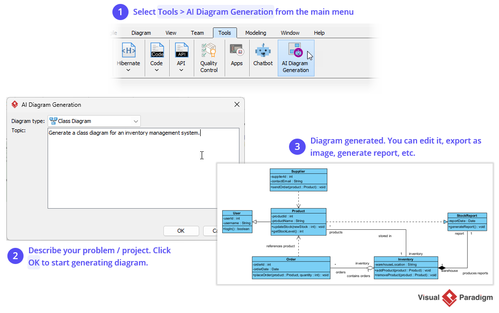
The process begins within the main application interface. Instead of navigating to a standalone plugin or external web service, the user accesses the tool directly from the Tools menu. This centralization ensures that the AI operates within the context of your current project environment.
- Navigate to the main menu bar.
- Select the Tools tab to reveal the specialized utility icons.
- Locate and click the AI Diagram Generation icon (identified by a purple circuit board symbol). This launches the dedicated AI interface.
Step 2: Defining the System Context
Once the dialog box is open, the system requires a Topic—a natural language description of the system you wish to model. The AI engine is designed to parse this text and infer the necessary entities, attributes, and relationships.
For this tutorial, we will use the following prompt to model an inventory management system:
💡 Did You Know?
The AI engine supports complex prompts involving multiple entities and relationships. You can specify not just the classes, but also the nature of their interactions (e.g., “Inventory manages multiple Products”) to generate accurate association multiplicities automatically.
Step 3: Analyzing the Generated Architecture
Upon clicking OK, the AI processes the prompt and renders a Class Diagram. This diagram is not merely a visual sketch; it is a structured data model ready for code generation or further refinement.
In the generated diagram, you will typically see:
- Entities (Classes): Blue boxes representing system objects such as
User,Product,Order, andInventory. - Attributes: Data properties defined for each class (e.g.,
orderId: int,productName: String). - Methods: Functional behaviors (e.g.,
placeOrder(product: Product, quantity: int)). - Relationships: Lines connecting classes that define how they interact, such as inheritance (dashed arrow), composition (diamond), and general associations.
Refining the Output
The power of Visual Paradigm’s AI lies in its iterative nature. Once the diagram is generated, it becomes a standard Visual Paradigm model. You can:
- Edit Manually: Drag and drop new classes or modify attributes if the AI missed a specific business rule.
- Export: Generate reports, export images, or reverse-engineer the diagram into code.
- Validate: Use the built-in quality control tools to ensure the generated model adheres to software engineering best practices.
By utilizing this workflow, teams can move from system requirements to architectural refinement in seconds, bridging the communication gap between technical and non-technical stakeholders.