


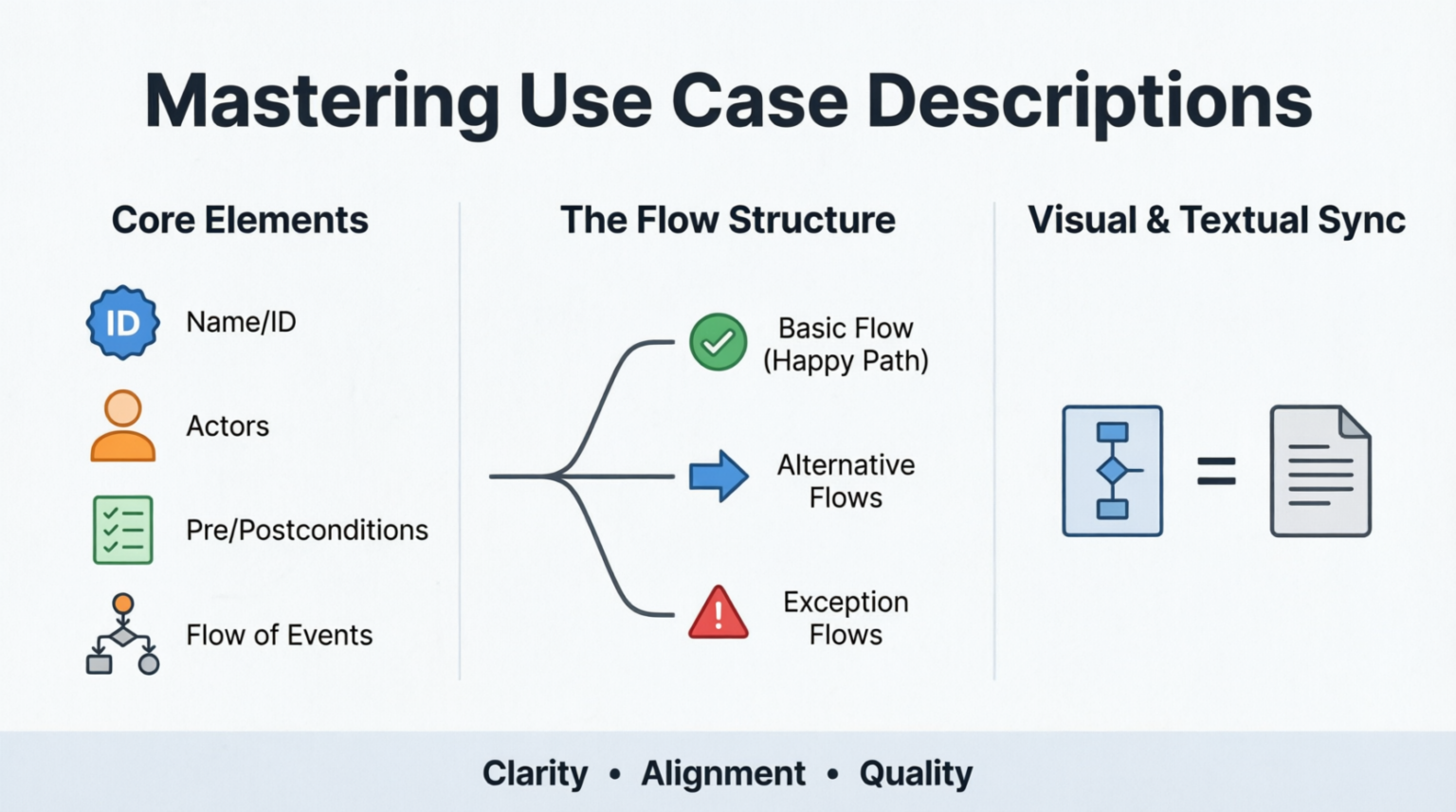
In the fast-paced world of software development, ambiguity is often the enemy of efficiency. While visual models like Use Case Diagrams provide a high-level overview of system functionality, they often lack the granular depth required for developers, testers, and stakeholders to fully understand how a specific feature should behave. This is where the Use Case Description becomes indispensable.
A use case description is a detailed, text-based narrative that captures the step-by-step interactions between an actor (a user or external system) and your system to achieve a specific goal. It serves as the textual counterpart to the visual use case diagram, bridging the gap between abstract concepts and concrete implementation. By clarifying functional requirements, aligning stakeholder expectations, and forming a robust foundation for testing, well-crafted use case descriptions ensure that everyone involved in the project shares a unified understanding of the system’s behavior.
The Dual Nature of Use Case Modeling
To understand the architecture of a robust software system, one must appreciate the complementary nature of modeling artifacts. The use case model is comprised of two primary components:
- The Use Case Diagram: The visual representation showing actors, use cases, and their relationships. It offers a “bird’s-eye view.”
- The Use Case Description: The textual details providing context, business rules, and specific flows. This is where the real value lies.
While the diagram illustrates what the system does, the description explains how it works. It provides the nuance, exception handling, and logic that a diagram alone cannot convey.
Core Elements of a Description
A well-written use case description typically includes the following standard sections to ensure clarity and completeness:
| Element | Description |
|---|---|
| Use Case Name & ID | A unique identifier and a verb-noun phrase (e.g., “Place Order”). |
| Brief Description | A concise summary of the purpose and the value delivered to the actor. |
| Actors | The primary actor initiates the interaction, while secondary actors provide services. |
| Preconditions | Conditions that must be true before the use case begins (e.g., “User is logged in”). |
| Postconditions | The state of the system after the use case finishes (success or failure). |
| Flow of Events | The step-by-step narrative detailing interactions. |
| Special Requirements | Non-functional requirements like performance, security, or regulatory constraints. |
The Flow Structure: Guiding the Logic
The heart of a use case description is the Flow of Events. This section is not a single monolithic list; it is a structured decision tree that covers all possible paths of execution. As visualized in the diagram, the flow branches into three distinct categories:
1. The Basic Flow (Happy Path)
This represents the “ideal” scenario where everything goes as planned. It documents the sequence of steps where the user successfully achieves their goal without encountering errors or interruptions. In the context of an online store, this would be a customer selecting an item, entering payment details, and receiving a confirmation.
2. Alternative Flows
These are less common, yet successful, paths to reach the goal. They often diverge from the basic flow to offer choices or handle variations. For example, a user might choose to pay via Credit Card (Alternative Flow A) or PayPal (Alternative Flow B) instead of the default method.
3. Exception Flows
This is the safety net of your documentation. Exception flows identify failure scenarios, such as validation errors, system unavailability, or network timeouts. These paths lead to an unsuccessful conclusion or an error state, documenting exactly how the system responds to handle the problem.
💡 Did You Know?
Standard UML guidelines recommend that every step in an “Alternative” or “Exception” flow must explicitly reference the step number in the Basic Flow where the divergence occurs. This cross-referencing is crucial for traceability during software testing and debugging.
Writing a Use Case Description: A Step-by-Step Guide
Creating a comprehensive use case description requires a structured approach. Follow this guide to ensure no critical detail is overlooked:
- Identify the Goal and Actors: Start by defining the specific goal the user wants to achieve. Ask: “Who is doing this, and why?” Define the primary actor clearly.
- Establish Pre- and Postconditions: Determine what must be in place for the use case to start (preconditions) and what the system’s state will be upon completion (postconditions). This sets the boundaries of the interaction.
- Write the Basic Flow: Document the “happy path” step-by-step. For each step, clearly describe who performs the action (actor or system) and what the system’s response is. Keep the language simple and active.
- Document Alternative Flows: Elicit other, less common ways to accomplish the same goal successfully. Note exactly where in the basic flow this alternative path would diverge (e.g., “At step 3…”).
- Define Exception Flows: Identify failure scenarios and document the system’s response, such as specific error messages displayed or rollback procedures.
Visualizing the Sync
The ultimate goal of this process is “Visual & Textual Sync.” The diagram acts as the index, pointing to the detailed descriptions. When you see a diamond shape in a flowchart or a decision node in a diagram, it corresponds to the branching logic found in your Use Case Description. By maintaining this alignment, you ensure that the visual architecture matches the logical implementation.
@startuml
skinparam packageStyle rectangle

title Use Case Visualization Sync

actor "Customer" as C
rectangle "Online Store" {
    usecase "Place Order" as UC1
    usecase "View Inventory" as UC2
}

C --> UC1
C --> UC2

note right of UC1
  Note: This diagram node corresponds to
  the text description in section 3.1.


  Basic Flow: 1. Select Item

  Exception: 1.1 Item out of stock
endnote
@enduml
By mastering these descriptions, you transform your system architecture from a static diagram into a dynamic blueprint for success.