


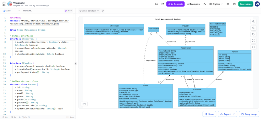
Creating robust software architecture diagrams can often be a tedious process involving manual drawing tools and tedious syntax adjustments. However, modern engineering platforms like VPasCode by Visual Paradigm are revolutionizing this workflow. This tutorial explores the architecture behind the Hotel Management System example, demonstrating how to leverage a real-time dual-panel editor to build professional UML Class Diagrams using the PlantUML Domain Specific Language (DSL).
The Architecture of the VPasCode Editor
The core innovation of this tool lies in its Real-Time Dual-Panel Editor. Unlike traditional Integrated Development Environments (IDEs) where you write code in one window and compile it to see a result in another, VPasCode operates entirely within the browser with zero local configuration.
The interface is split into two distinct, synchronized panels:
- The Left Panel (The Source): This is your dedicated code editor. Here, you write pure text scripts using PlantUML syntax. It handles DSL scripts, imports, and structural definitions.
- The Right Panel (The Engine): This is a high-performance rendering engine. It parses the text from the left and instantly updates the interactive canvas. There is no “save” or “refresh” button required; the feedback loop is immediate.
Step-by-Step: Building the Hotel Management System
To understand the modeling concepts, we will deconstruct the code shown in the screenshot. This example demonstrates how to define interfaces, abstract classes, and relationships between entities.
1. Setup and Imports
Every PlantUML diagram begins with the @startuml directive. We also see a critical inclusion of the Visual Paradigm library. This allows the rendering engine to use specialized themes and styling options that standard PlantUML might not support out of the box.
@startuml
!include https://static.visual-paradigm.com/web/resources/plantuml-stdlib/themes/vp.puml
title Hotel Management System
2. Defining Interfaces
In object-oriented design, interfaces define a contract that classes must follow. In the diagram, we define two interfaces: IReservable and IPayable.
The code uses the interface keyword followed by the name, and curly braces {} to define the methods within the contract.
' Define interfaces
interface IReservable {
    + makeReservation(customer: Customer, dates: DateRange): boolean
    + cancelReservation(reservationId: String): boolean
    + checkAvailability(date: Date): boolean
}

interface IPayable {
    + processPayment(amount: double): boolean
    + issueRefund(reservationId: String): boolean
    + getPaymentStatus(): String
}
3. Creating Abstract Classes and Attributes
Abstract classes are used to provide a common definition of a base class that multiple derived classes can share. In our example, Person is an abstract class containing general attributes like ID, name, and email.
Notice the syntax for attributes and methods:
-denotes private visibility.+denotes public visibility.- The colon
:separates the name from the data type.
' Define abstract class
abstract class Person {
    - id: String
    - name: String
    - email: String
    - phone: String
    + getId(): String
    + getName(): String
    + getContactInfo(): String
    + updateContactInfo(info: String): void
}
4. Implementing Concrete Classes
The Reservation class is the core of the system. It inherits from both IReservable and IPayable. In PlantUML, this relationship is represented using the implements keyword. This tells the rendering engine that Reservation must provide implementations for all methods defined in those interfaces.
class Reservation {
    - reservationId: String
    - checkInDate: Date
    - checkOutDate: Date
    - totalPrice: Double
    - status: ReservationStatus
    - specialRequests: String
    - calculateTotalPrice(): double
    - confirmReservation(): void
    - checkIn(): void
    - checkOut(): boolean
    - updateOrder(newCheckIn: Date, newCheckOut: Date): String
    + getDuration(): int
}
5. Modeling Relationships
The most complex part of a Class Diagram is defining how objects relate to one another. The diagram uses standard UML line styles and arrows:
- Inheritance: The
Personclass is extended byCustomer, indicated by a solid line with a hollow triangle. - Association:
Customer“makes” aReservationand “booked” by aRoom. - Composition/Aggregation: The diagram shows that a
Reservation“contains” aRoom.
The syntax for these relationships typically follows the pattern: ClassA --> ClassB : "relationship label".
' Relationships
Reservation "1" -- "*" Room : contains
Customer --> Reservation : makes
Reservation --> Room : booked by
Customer --|> Person : extends
Conclusion
By utilizing the VPasCode tool, developers can focus on the logic and structure of their system architecture rather than the mechanics of drawing shapes. The immediate feedback loop provided by the right-panel rendering engine ensures that the code you write perfectly matches the visual diagram you see, eliminating the “save-and-refresh” cycle common in older modeling tools.